#define pulseHigh(pin) {digitalWrite(pin, HIGH); digitalWrite(pin, LOW); }
#define RESET 13  // Pin 13

void setup() {
pinMode(13, OUTPUT);
}

void loop() {

      digitalWrite(13,HIGH);
      delay (3000);
      digitalWrite(13,LOW);
      delay (1500);
      dash();dash();dot();space();
      dot();dash();space();
      dot();dot();dot();space();
      dot();dot();dot();dot();space();
      delay(2000);


      pulseHigh(RESET); // off
};


void dot()
{
  digitalWrite(13,HIGH);
  delay(100);
  digitalWrite(13,LOW);
  delay(100);

}

void dash()
{
  digitalWrite(13,HIGH);
  delay(300);
  digitalWrite(13,LOW);
  delay(100);

}

void space()
{
  digitalWrite(13,LOW);
  delay(300);
}
I checked and saw at http://www.heywhatsthat.com/?view=PKDC86DD that the path from Adler Planetarium to the Point was just a touch over five miles and free. I could identify the Point fairly well in binoculars; I aimed the laser pointer by fixing to a tripod, testing the aiming by hitting nearer objects (a beach buoy nearby happened to be retroreflective which helped quite a bit) and then carefully moving the system towards the Point. I turned it off whenever boats went near the beam. To prove it was me, the judge requested I manually hit the key a few times--since I had only a programmed 'SCAV' (yes, it says GASH above), I manually connected the pointer to 5V & ground on the Arduino. It was powered via a 12V battery and a cigarette lighter USB charger to provide 5.1V.
Showing posts with label diy. Show all posts
Showing posts with label diy. Show all posts
Wednesday, June 24, 2015
Morse code over laser light with an Arduino
19.
After another of my famously lavish parties, I sometimes walk alone out to Promontory Point at exactly
10:00 p.m. Thursday and glance lakeward, out at a blinking light on some distant shore, and think of
Daisy Buchanan. That light winks on and off, unattainable, a powerful metaphor for|wait, is that
Morse code? [5 points for lights over a mile away; 15 points for lights over 5 miles away; 0 points for
lights that are only metaphors]
For this Scav Hunt item I used an Arduino to turn a laser pointer on and off in morse code:

Thursday, June 27, 2013
lemon juice and fine steel wool works on rust on a stainless steel dishwasher
I had a rust stain on the interior of a stainless steel dishwasher from contact with a rusting pan, and after having no success with CLR and just a paper towel, I applied some lemon juice, let it sit a few minutes, and then gently rubbed with #0000 fine steel wool, and the stain was removed. I suspect the magic was the steel wool. I did test it in an inconspicuous space to make sure I wasn't going to scratch up the surface. I noted that GE approved citric acid for stainless steel dishwashers beforehand.
Wednesday, February 13, 2013
Why toolboxes and tool handles stink.
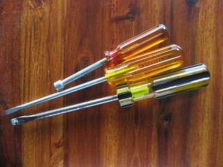
For years I've encountered this issue, and it always perplexed me: why do a lot of toolboxes stink? I had always assumed it was related to heavy use with sweat and dirt and zero cleaning, but after I started encountering it on my own, barely used tools, I started looking into it. You can find some posts on DIY forums asking the same question, and how they could never clean the toolbox well enough to get rid of the stink.
Eventually I found someone who pointed out it was coming from the tool handles, and then they pointed out the culprit: tool handles made of Cellulose Acetate Butyrate. A thermoplastic, it offers excellent UV and solvent resistance that cellulose acetate doesn't offer. And it feels in the hand like a natural substance, something that is almost intangible, like a tool that is made by craftsmen, a characteristic that a polyethylene or polypropylene handle does not have. CAB also offers no splinters like the older wood handles. It also can be very clear. And when that plastic begins to degrade, it releases free acetic acid and butyric acid.
The odor of vinegar is a familiar sign to those in the film and photographic business; the cellulose acetate backing of film releases it as it degrades. I once visited a famous photographer's house and his office where he stored his negatives had that acrid odor--while for a photographer it reminds you of the darkroom, the midpoint of the creative process, it also brings to you vividly the end of the process--the decay of the work.
The butyric acid, one of the carboxylic acids, with a formula of CH3CH2CH2COOH, just smells like, in polite company like parmesan cheese, or like rancid butter or vomit. It's not nice above a certain concentration. Once I discovered this I immediately spent a little time sniffing each tool I had, and in short order discovered the ones that are the problem. They immediately got isolated from the rest, because the free butyric acid really does migrate and make everything unpleasant. I thought about giving the tools away, but really, who wants such a tool, even if free? I was going to throw them out, but that made me feel bad. And I think I've found a solution to stinky tools. I carefully fully coated the handles in two coats of shellac, a natural sealer, and now they don't smell to my nose.
Wednesday, February 08, 2012
First Cigar Box Guitar build
 A few photos of my first cigar box guitar. For cigar boxes both Hyde Park Cigars (the place on 53rd and Harper) and Binny's have them, although the latter's supply is variable. The neck is 1x2 poplar from home depot. I bought the tuning pegs for about $10 from C.B Gitty and the strings online. The saddle is a hard drive spindle top as are the coverings on the sound holes. The bridge and neck are just pieces of the cigar box. There is a piezo pickup inside.
So, the errors made in this build were: the holes drilled for the tuning pegs need to be aligned better. I drilled 1/4" holes with a forstner bit; these fit the pegs perfectly but not the little bushings-and the next biggest size was too big, leaving the lowest tuner a little bent. The neck doesn't hold the strings--I made a notch for each string but the highest string is too loose in the notch. The cigar box wood is too light for this. I cut out the cigar box to fit the neck but forgot about the box top so the box can interfere with fretting. I think a fret board might help. I wired the piezo backwards but no apparent harm; I'd like to experiment with positioning and how to attach them.
I can't play, but it was easy, fun, and now I've got a cigar box guitar! I can't wait to improve upon it with another one.
A few photos of my first cigar box guitar. For cigar boxes both Hyde Park Cigars (the place on 53rd and Harper) and Binny's have them, although the latter's supply is variable. The neck is 1x2 poplar from home depot. I bought the tuning pegs for about $10 from C.B Gitty and the strings online. The saddle is a hard drive spindle top as are the coverings on the sound holes. The bridge and neck are just pieces of the cigar box. There is a piezo pickup inside.
So, the errors made in this build were: the holes drilled for the tuning pegs need to be aligned better. I drilled 1/4" holes with a forstner bit; these fit the pegs perfectly but not the little bushings-and the next biggest size was too big, leaving the lowest tuner a little bent. The neck doesn't hold the strings--I made a notch for each string but the highest string is too loose in the notch. The cigar box wood is too light for this. I cut out the cigar box to fit the neck but forgot about the box top so the box can interfere with fretting. I think a fret board might help. I wired the piezo backwards but no apparent harm; I'd like to experiment with positioning and how to attach them.
I can't play, but it was easy, fun, and now I've got a cigar box guitar! I can't wait to improve upon it with another one.
Sunday, April 17, 2011
Re: Magnetic Cable holders
Well, I had one issue with my magnetic cable holder: an incompatibility between the hot glue and the adhesive on a particular 'model' of holder. The ones with the adhesive and foam backing cleanly separated from the hot glue after a week or so under a slight load. I scraped the foam and adhesive off and reattached the magnet and the holder. I think part of the problem was difficulty in getting the hot glue thin enough before it set--this is a problem when attaching it to metal surfaces, which act as very efficient heatsinks. But other problem is the glue was not too gluey.
I've come across this incompatibility between hot glue and a few surfaces. The ubiquitous hot glue is EVA: Ethylene-Vinyl Acetate, a thermoplastic. I still need to make sure the adhering surfaces are hot glue compatible. It's really more about the convenience of the glue gun than anything else. I suppose I should be using a more universal glue for my generic adhesive requirements.
I've come across this incompatibility between hot glue and a few surfaces. The ubiquitous hot glue is EVA: Ethylene-Vinyl Acetate, a thermoplastic. I still need to make sure the adhering surfaces are hot glue compatible. It's really more about the convenience of the glue gun than anything else. I suppose I should be using a more universal glue for my generic adhesive requirements.
Wednesday, March 16, 2011
Geiger Counter back up
My long-suffering Geiger counter is now back up and running.
http://www.lib.uchicago.edu/~dean/float.htm.
Now, as has been pointed out, this particular instance of this experiment is really an experiment, and is run only by me, for only experimental purposes. It doesn't represent any opinion or endorsement or opinion of any entity, whether the University of Chicago Library or the University or anything else. It is not a service. It represents nothing, is not calibrated, and should not be relied upon by anyone for anything. Don't email or call anyone but myself about it.
This instance is located in my office on the A-level of the Regenstein Library, the first basement level of a six-story building. The levels average about 8 microrads/hr here. Outside at Ryerson Physical Laboratory on the fifth floor, levels average to about 12 microrads/hr, which indicate the shielding provided by the Regenstein against the cosmic ray flux.
The problem I've been having with this counter was with the associated AW-SRAD software, which runs under DOS, doesn't appear to support virtual COM ports above COM4. On my Windows XP PC I had installed an Arduino which offered a similar USB Serial converter and I theorize at some point there was a conflict and the Geiger counter with its FTDI USB to serial converter took a high COM port at COM5. After removing the Arduino, I then disabled the real serial port at COM1 and forced via Device Manager->Ports->USB Serial Ports the port to go to COM1.
http://www.lib.uchicago.edu/~dean/float.htm.
Now, as has been pointed out, this particular instance of this experiment is really an experiment, and is run only by me, for only experimental purposes. It doesn't represent any opinion or endorsement or opinion of any entity, whether the University of Chicago Library or the University or anything else. It is not a service. It represents nothing, is not calibrated, and should not be relied upon by anyone for anything. Don't email or call anyone but myself about it.
This instance is located in my office on the A-level of the Regenstein Library, the first basement level of a six-story building. The levels average about 8 microrads/hr here. Outside at Ryerson Physical Laboratory on the fifth floor, levels average to about 12 microrads/hr, which indicate the shielding provided by the Regenstein against the cosmic ray flux.
The problem I've been having with this counter was with the associated AW-SRAD software, which runs under DOS, doesn't appear to support virtual COM ports above COM4. On my Windows XP PC I had installed an Arduino which offered a similar USB Serial converter and I theorize at some point there was a conflict and the Geiger counter with its FTDI USB to serial converter took a high COM port at COM5. After removing the Arduino, I then disabled the real serial port at COM1 and forced via Device Manager->Ports->USB Serial Ports the port to go to COM1.
Thursday, March 10, 2011
Audio stereo isolation circuit diagram
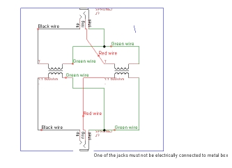
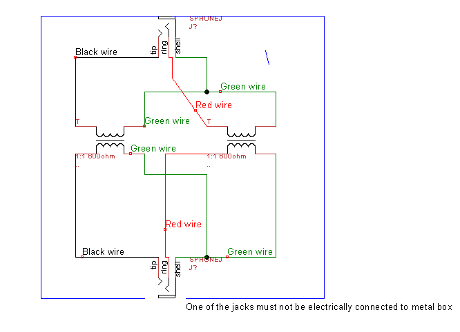
Two years I made an audio stereo isolation transformer, suitable for getting rid of ground loop problems in a line-level audio connection. Here's a simple circuit diagram that attempts to match the colors of the physical device.
http://www2.lib.uchicago.edu/~dean/blog/isolation-transformer.dsn
Circuit diagram for TinyCAD.
http://www2.lib.uchicago.edu/~dean/blog/isolation-transformer.dsn
Circuit diagram for TinyCAD.
Tuesday, January 25, 2011
Making Things Talk & Processing projects
I got Making Things Talk as a gift from a great friend of mine and I just ran two of the projects in the "Identification" chapter.
To start off, you install Processing, a free language for visualization. For me the download for Windows was here. It's a slightly different install process than usual; just make a directory like "C:\Program Files\processing-1.2.1" and dump the contents there, and make a shortcut to processing.exe somewhere convenient for you (or you will forget it's installed).
Then in order to do video things you first need to have quicktime installed; if you have iTunes then you've got quicktime. And, finally, you need a VDIG implementation; for Windows it is WinVDIG. Install version 1.01 from here.
The first project was finding a particular color in a webcam image, reading the color, then putting a pointer on that spot.
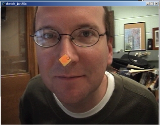
Hey it works! See the dot on my nose?
The screenshot misses the dynamic aspect of the little dot following you around.
The second project was using your imager to decode QR Codes--and ha ha, check out the sample from the book. Nice one, Tom Igoe.
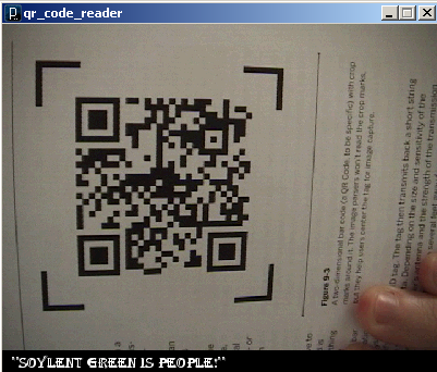
Great stuff.
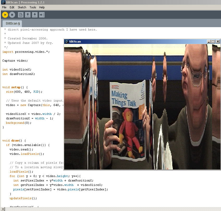
P.S. I just loaded the 'slitscan' example from the Processing examples. Ha!
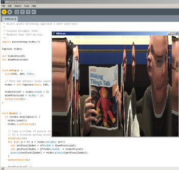
To start off, you install Processing, a free language for visualization. For me the download for Windows was here. It's a slightly different install process than usual; just make a directory like "C:\Program Files\processing-1.2.1" and dump the contents there, and make a shortcut to processing.exe somewhere convenient for you (or you will forget it's installed).
Then in order to do video things you first need to have quicktime installed; if you have iTunes then you've got quicktime. And, finally, you need a VDIG implementation; for Windows it is WinVDIG. Install version 1.01 from here.
The first project was finding a particular color in a webcam image, reading the color, then putting a pointer on that spot.
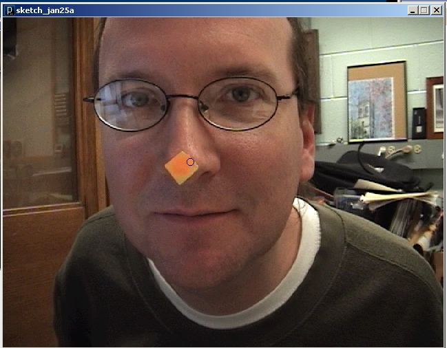
Hey it works! See the dot on my nose?
The screenshot misses the dynamic aspect of the little dot following you around.
The second project was using your imager to decode QR Codes--and ha ha, check out the sample from the book. Nice one, Tom Igoe.
Great stuff.
P.S. I just loaded the 'slitscan' example from the Processing examples. Ha!
Wednesday, January 27, 2010
Joule Thief: a simple DC voltage booster
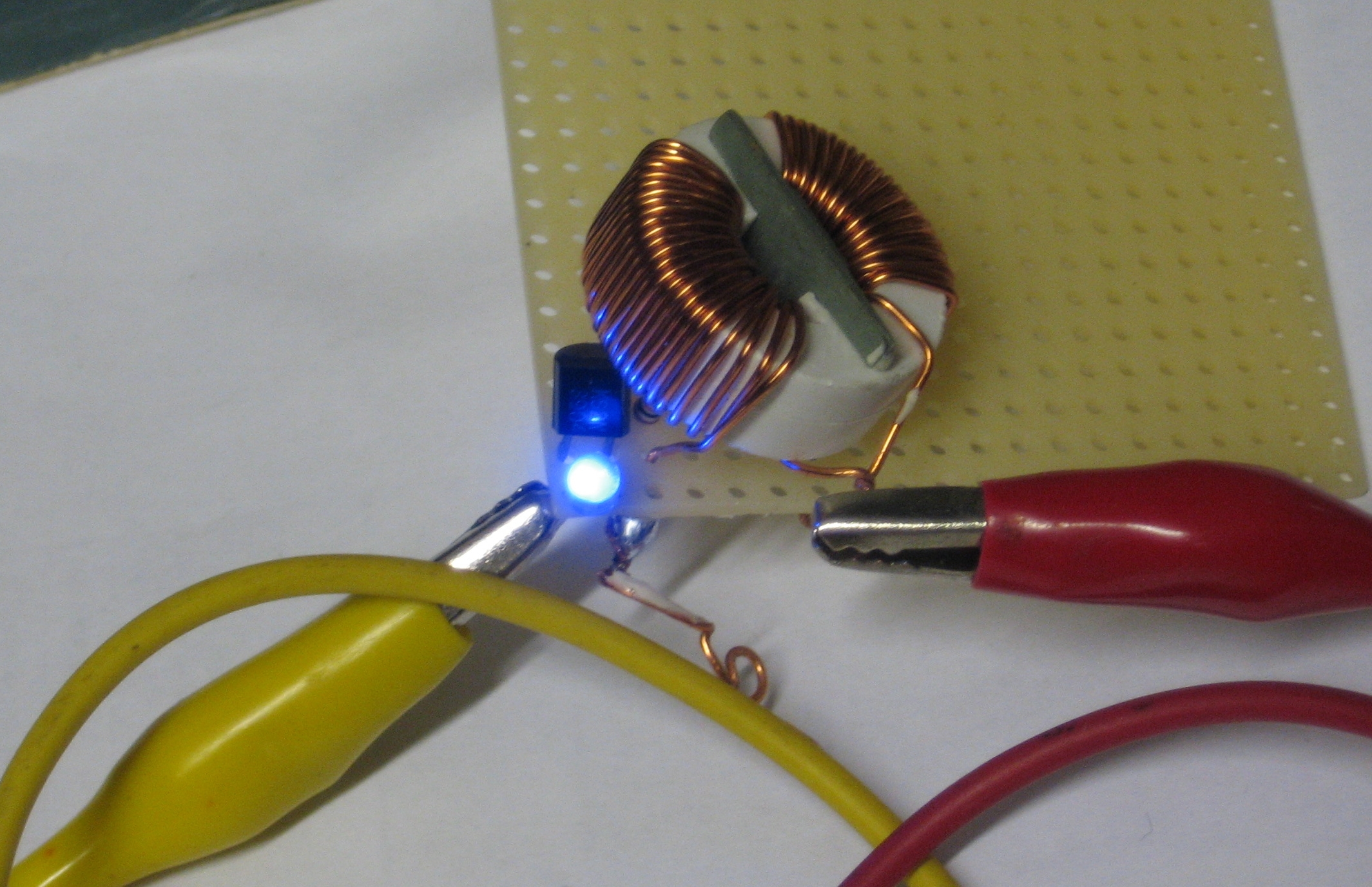
A joule thief circuit lit from a 0.5V AAA battery. Click to enlarge.
A Joule thief is a simple circuit that acts as a DC to DC booster, raising a supply voltage by several volts. In this iteration it uses the exhausted voltage of a alkaline battery and boosts it enough to light a blue LED that requires 2.8V to light. With an otherwise dead 0.5V AAA battery, it will light a blue LED and run for days, using (at the moment) just under 2mA of current. It's much much dimmer than using a fresh battery or running the LED with a proper current through it. Giving the Joule thief circuit 3V from two fresh batteries pulls 75mA through the LED, making it very, very bright and probably short-lived.
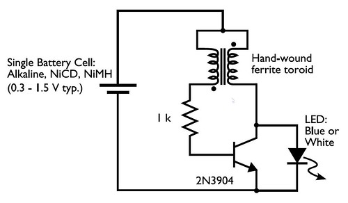
A schematic is below. The circuit works like this: When first turned on, current flows into the inductor and produces a magnetic field in the toroid. While this is happening, no voltage appears at the base of the transistor, so the transistor remains off. The LED sees at first no voltage and while the inductor fills up, it only sees a maximum voltage of the battery, which is not enough to pass the diode. Once the inductor is charged, the battery voltage appears at the base of the transistor, turning it on. This allows the right side of the inductor to want to dump the energy it has stored in its magnetic field as quickly as possible, and this gives us a high-voltage that appears across the inductor. When that voltage exceeds 2.8V the LED turns on and lights up until the voltage drops below, triggering the sequence to begin again. I measured the frequency of the on/off oscillation and it seems to run at about 34kHz; the multimeter said between 68 and 72kHz but a radio showed there was 34kHz signal as well, which I assume was the fundamental (and the 68kHz one a harmonic). It did change in frequency a bit while on.
 Bre Pettis/Windell Oskay
Thursday, December 24, 2009
Halogen resistance
If you are curious, the resistance of a 300W type J halogen bulb, the ones you would find in those halogen torchiere lamps, is 3.3 ohms when cold. When it's hot it is 48 ohms, but that's a calculation only based on the wattage.
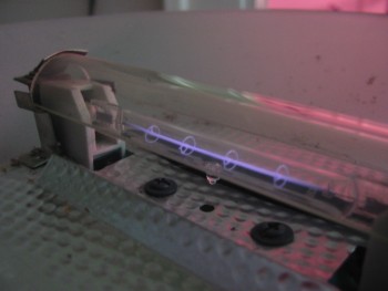
A warm halogen bulb in the near infrared
Since converting such a torchiere to CFL (but not in this project), I had an extra halogen bulb and debated throwing it out, but I figured they might make a decent power resistor. I used it in a project converting a PC ATX power supply to a benchtop 12V source. It works--but the hassle of cleaning the contacts for soldering, soldering, and placing such a large object in the case was enough to decide buying a power resistor in the first place is probably easier.
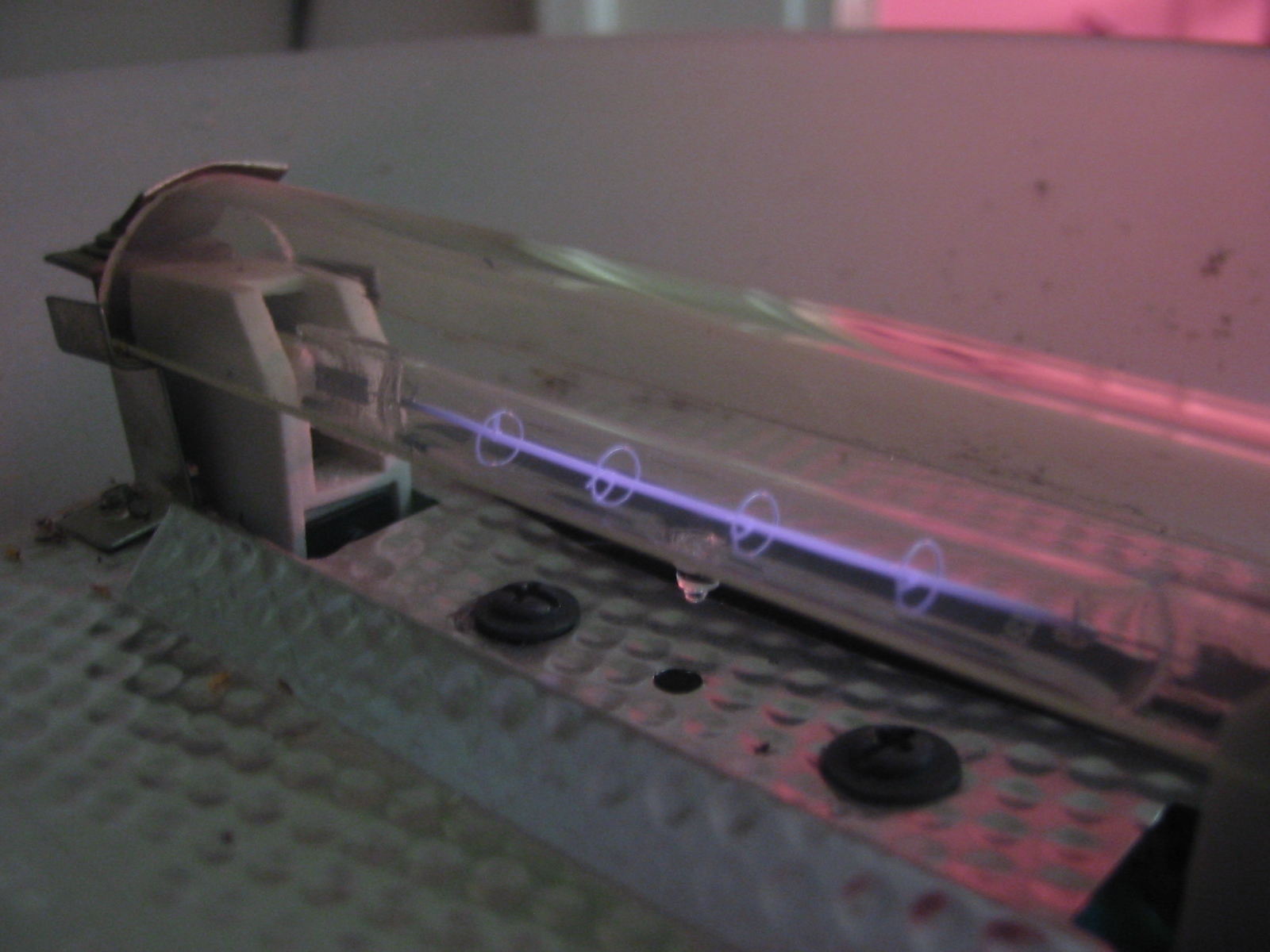
A warm halogen bulb in the near infrared
Since converting such a torchiere to CFL (but not in this project), I had an extra halogen bulb and debated throwing it out, but I figured they might make a decent power resistor. I used it in a project converting a PC ATX power supply to a benchtop 12V source. It works--but the hassle of cleaning the contacts for soldering, soldering, and placing such a large object in the case was enough to decide buying a power resistor in the first place is probably easier.
Monday, June 08, 2009
Audio isolation transformer
I used to record audio off my Tivo on my desktop computer--but when I had the cable TV connected, I would get a loud hum. The reason for this is related to the idea of "ground" in electrical systems, which are used as a reference point for zero voltage and/or safety purposes. The kicker was the cable TV cable offered a different path to ground compared to the PC's ground.
For consumer generic audio connections, the audio signal (a varying AC voltage of about one volt) is compared to the ground of the system. Hence the two connectors on an RCA connector, signal and ground, or three connectors on a stereo jack: left, right, and ground. If your ground happens to be varying up and down at 60 times a second (because it's not a good ground, for instance), you will also get that hum on your output.
For some professional audio systems, the reference ground is brought with the signal, so you have three connections for any channel. When both the signal and ground vary up and down in sync, it's easy to subtract the pickup noise and have a clean signal.
In simple, single systems, either approach works fine. The problem is when you start interconnecting equipment.
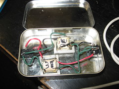
I made a stereo isolation audio transformer to solve this problem. The left and right channels enter a 1:1 600ohm audio transformer, which transmits the audio signal (which is AC) but blocks any DC connection. This prevents ground loops and currents between the two devices. I got the two transformers from old modems. One of the jacks is a fancy panel mount, the other is from an old sound card, and this old one is actually needed, because it is plastic, isolating it from the case, which is connected to the ground of the panel mount jack. Of course, I put everything in an Altoids tin.
I suppose it would also help if I put some ferrite on the inputs to also reduce RFI/EMI problems, but I haven't yet. Just having this device between a shortwave radio and a PC has reduced interference pickup quite a bit.
You can see more photos of the build at http://www.flickr.com/photos/dwarmstr/sets/72157604679420753/. Essentially, 1. Measure and Mark your holes. 2. Make a small punch to keep drill centered. 3. Drill a pilot hole, then the right size. 4. Solder the connections. I used a multimeter to figure out which connection was which on the transformers. 5. Hot glue for stability.
Parts cost: about $2.50 for the 3.5mm stereo panel mount. Everything else I scrounged for from old parts, not counting my time. Here's the equivalent commercial product at $32: http://www.amazon.com/3-5mm-Stereo-Audio-Isolation-Transformer/dp/B001GUS7EO. I do enjoy the look of that commercial case.
For consumer generic audio connections, the audio signal (a varying AC voltage of about one volt) is compared to the ground of the system. Hence the two connectors on an RCA connector, signal and ground, or three connectors on a stereo jack: left, right, and ground. If your ground happens to be varying up and down at 60 times a second (because it's not a good ground, for instance), you will also get that hum on your output.
For some professional audio systems, the reference ground is brought with the signal, so you have three connections for any channel. When both the signal and ground vary up and down in sync, it's easy to subtract the pickup noise and have a clean signal.
In simple, single systems, either approach works fine. The problem is when you start interconnecting equipment.
I made a stereo isolation audio transformer to solve this problem. The left and right channels enter a 1:1 600ohm audio transformer, which transmits the audio signal (which is AC) but blocks any DC connection. This prevents ground loops and currents between the two devices. I got the two transformers from old modems. One of the jacks is a fancy panel mount, the other is from an old sound card, and this old one is actually needed, because it is plastic, isolating it from the case, which is connected to the ground of the panel mount jack. Of course, I put everything in an Altoids tin.
I suppose it would also help if I put some ferrite on the inputs to also reduce RFI/EMI problems, but I haven't yet. Just having this device between a shortwave radio and a PC has reduced interference pickup quite a bit.
You can see more photos of the build at http://www.flickr.com/photos/dwarmstr/sets/72157604679420753/. Essentially, 1. Measure and Mark your holes. 2. Make a small punch to keep drill centered. 3. Drill a pilot hole, then the right size. 4. Solder the connections. I used a multimeter to figure out which connection was which on the transformers. 5. Hot glue for stability.
Parts cost: about $2.50 for the 3.5mm stereo panel mount. Everything else I scrounged for from old parts, not counting my time. Here's the equivalent commercial product at $32: http://www.amazon.com/3-5mm-Stereo-Audio-Isolation-Transformer/dp/B001GUS7EO. I do enjoy the look of that commercial case.
Sunday, January 25, 2009
Microwave meter videos
I made a few videos of the simple microwave / 2.4GHz meter dealing with work office's microwave oven--woe be unto whomever hangs around the hinge.
The first is a full examination of the space of the microwave oven, and is entirely inappropriate for those with short attention spans (stick to the second video, you).
This one is a short proof the detection is when the microwave oven is busily heating my hot water for tea.
The other amazing news is there is a very strong microwave signal that the northwest corner of the roof of Ryerson intercepts that appears to be coming from either the Admin building or the hospital: it strongly peaks in the southwest direction, almost pegs the meter on the 200mV scale, and when I added a headphone to the meter I could audibly hear some sort of signal that reminded me of a TV video sync noise.
What is this signal? Am I hearing a horizontal sync? Or is there some other signal that has a repetitive sync noise that runs at 12-18 kilohertz?
The first is a full examination of the space of the microwave oven, and is entirely inappropriate for those with short attention spans (stick to the second video, you).
This one is a short proof the detection is when the microwave oven is busily heating my hot water for tea.
The other amazing news is there is a very strong microwave signal that the northwest corner of the roof of Ryerson intercepts that appears to be coming from either the Admin building or the hospital: it strongly peaks in the southwest direction, almost pegs the meter on the 200mV scale, and when I added a headphone to the meter I could audibly hear some sort of signal that reminded me of a TV video sync noise.
What is this signal? Am I hearing a horizontal sync? Or is there some other signal that has a repetitive sync noise that runs at 12-18 kilohertz?
Wednesday, December 17, 2008
a very simple 2.4GHz meter
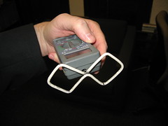
I built a very simple meter that reads the strength of radio energy in its vicinity, without amplification or anything fancy. It picks up radio waves roughly around 1 to 3 gigahertz. It does very well in detecting cell phones, microwave ovens, and wireless access points.
On a simple level, the antenna converts radio waves into an electrical AC voltage, which is then converted by the germanium diode into a pulsing DC voltage. A capacitor stores the pulses and smooths out the pulsing and leaves a very small DC voltage, which is measured directly at a tiny multimeter I picked up at American Science and Surplus. I set the meter to DC voltage, 200mV scale.
The biquad antenna is sensitive to vertically polarized waves and slightly directional as well. A lot of designs also stick a ground plane behind it to increase the directionality, but I was looking for more of a field strength probe, rather than having an antenna that got me the most gain. It's a trade-off since the detector is so simple and without amplification, but that's what you get.
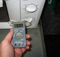
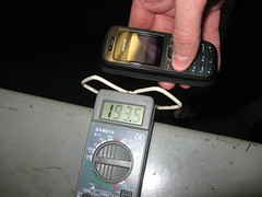
What can we measure with this meter? My standard test suite for gigahertz-ish radio frequencies is delinquent*, so all I can think of is cell phones, microwave ovens, and wireless networking. I found that the office microwave oven puts much more energy out at the hinge side of the door and a fan vent on the side than it does the meshed window. It can saturate the meter at the 200mV scale (when right next to the fan vent). Cell phones periodically check in with their towers (you can also tell this with a set of computer speakers anywhere near a GSM phone). They also do put out a bit of gigahertz radiation; I can detect them sending text messages from about six feet away and more when talking--they can also reach 200mV. Wireless 802.11b and g networks are actually pretty low-power in the scheme of things--they hard to see except close-up until they are transmitting data; then I can detect them six or so feet away. During idle they emit a "beacon" 10 times a second. The wifi antennas are also a good source for checking the polarization of the biquad--I get nearly nothing from them if I rotate the receiving antenna 90 degrees.
Outside the signal level varies greatly. There is a pervasive field which is presumably cellular networks and the addition of all the 802.11b/g/n networks. On the University of Chicago campus near the Regenstein Library the average strength varies from 0.2mV to 0.6mV, with a couple of spikes to 1.0mV. There are also areas of much stronger than ambient. For instance, outside of the Medici on 57th street the average field strength is 2-3mV and peaks at moments at 8mV. There are cellular tower antennas on a school across the street; so it seems likely the area is getting a particular sector of the tower.
I used this Field Strength Meter for 2.4 Ghz Wireless LAN as the excellent template for the project. For my version I used a standard 1N34A germanium diode--this is a more sensitive diode, and turns on at 0.3V instead of 0.6V like a standard silicon diode. I painted the diode black, as the diode proved to be photo-sensitive (all PN junctions are light-sensitive, and ones in transparent glass tubes even more so). Also, I didn't tune the capacitance at all. I then ran two wires to the inside plugs and drilled a hole in the case and hot-glued the antenna to the front of the meter. It's nice and compact, although the GP23A 12V battery in it doesn't last very long.
I could see easy modifications of this system, putting a simple FET amplifier or such to increase the meter response. If I use one of the inexpensive multimeters from Harbor Freight I might have enough room for a prebuilt circuit and a more directional antenna. I'd also like to see if I can pick up both aviation and weather radars with such a simple system. Maybe I should make a Sardine Can antenna?
*delinquent is also a synonym for nonexistent.
Sunday, October 19, 2008
Scanner Camera color
If you could synchronize a tri-color set of filters with the RGB set of LEDs in the Canon Canoscan scanner, you could produce color images with a single scan of the diy scanner cameras out there.
Wednesday, April 23, 2008
Rockefeller Chapel, Reynolds Club, and Flowers

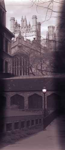
The light was rapidly falling last evening and this was my last image, with a full open aperture, but it was still underexposed by about a stop. Expressed in other terms, a film camera with 100ASA film would expose for this for about one second at f/8. Autoleveled and hue adjusted in photoshop. See the original here. This also was the first outing of the camera with a coat of black paint in the interior, an additional baffle on the top to handle light when doing macro work, and I added a shoulder strap with some eyelets (one broke on the trip). Remind me to stick some teflon strips or wax the bottom of the inner box--it's getting too hard to move to focus.

A color image, underexposed. The lightest of breezes moved the daffodils a touch between exposures. The flowers were just over 4 feet away.
Tuesday, April 22, 2008
CF Torchiere replacement
Compact Fluorescents are all hot right now. And it's Earth Week.
I bought a floor lamp from Home Depot that used a single standard bulb and didn't have any fancy dimmer system: it just had a hi/lo switch (I'm still not sure what it does with it--the CFLs flicker on the low setting, so I quickly turn the lamp to high when flipping the switch. It could be a simple rectifier to provide 50% of the power). I then bought three lamp socket splitters. These screw into a standard lamp socket and provide two sockets. So, with three splitters, a single socket becomes four. This is OK because the CFLs use so much less power--with four of them, I'm only using 100W, and the floor lamp suggests using a 150W standard bulb. The sockets themselves are rated higher, so I think the 150W max is for thermal/fire issues (high wattage bulbs can start fires if drapery or other flammables fall on them).
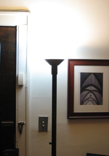
Taking pictures of lighting fixtures is hard--either the fixture looks dim and the room dark, or the fixture is overexposed.
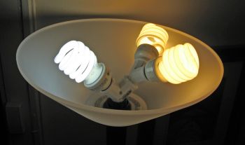
If you think the color temperature is off, you can adjust by using different color CF bulbs. Here was an experiment with a 2:1 warm:daylight ratio.
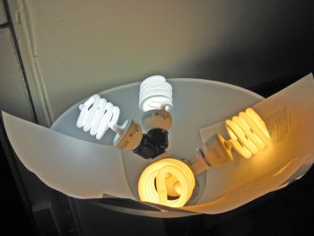
an even ratio between warm and daylight. This was too cool for evening use. The color is way exaggerated here--the yellow bulbs are nearly white to the eye.
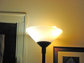
The color of the photographs is too strong--your eye does not see such strong color in the fixture.
In any case, I made this fixture 100% n:vision 100W soft white bulbs, and use it all the time. I have a second fixture where I replaced the dimmer switch with a standard push switch (it's tough to find a switch that fits in small diameter torchieres) so I could use compact fluorescents in it. I put 3 GE 100W daylight bulbs in the latter fixture and use it only during the day.
Now the caveat: the splitters stick the bulbs higher than where an incandescent would be in the fixture. Ideally the rim of the lamp shade would be a touch higher, but I've yet experimented with the right material to make one. Doing so would improve the fixture and reduce glare from it.
The end result is I've increased the lighting in my otherwise dark apartment (north facing windows on the first floor) and decreased my lighting energy usage by 50%, even more on average since I don't use the second fixture at night. I'm already being paid back on my electricity bill: some $10 a month less.
I bought a floor lamp from Home Depot that used a single standard bulb and didn't have any fancy dimmer system: it just had a hi/lo switch (I'm still not sure what it does with it--the CFLs flicker on the low setting, so I quickly turn the lamp to high when flipping the switch. It could be a simple rectifier to provide 50% of the power). I then bought three lamp socket splitters. These screw into a standard lamp socket and provide two sockets. So, with three splitters, a single socket becomes four. This is OK because the CFLs use so much less power--with four of them, I'm only using 100W, and the floor lamp suggests using a 150W standard bulb. The sockets themselves are rated higher, so I think the 150W max is for thermal/fire issues (high wattage bulbs can start fires if drapery or other flammables fall on them).

Taking pictures of lighting fixtures is hard--either the fixture looks dim and the room dark, or the fixture is overexposed.
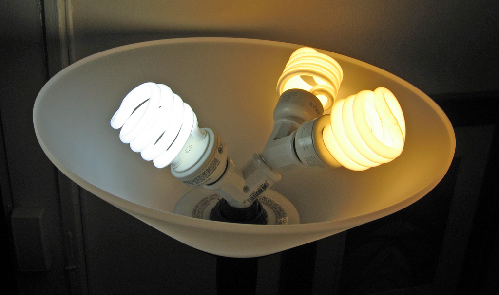
If you think the color temperature is off, you can adjust by using different color CF bulbs. Here was an experiment with a 2:1 warm:daylight ratio.
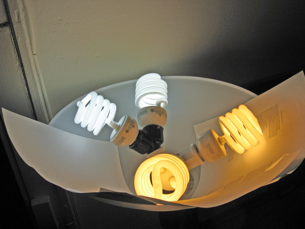
an even ratio between warm and daylight. This was too cool for evening use. The color is way exaggerated here--the yellow bulbs are nearly white to the eye.

The color of the photographs is too strong--your eye does not see such strong color in the fixture.
In any case, I made this fixture 100% n:vision 100W soft white bulbs, and use it all the time. I have a second fixture where I replaced the dimmer switch with a standard push switch (it's tough to find a switch that fits in small diameter torchieres) so I could use compact fluorescents in it. I put 3 GE 100W daylight bulbs in the latter fixture and use it only during the day.
Now the caveat: the splitters stick the bulbs higher than where an incandescent would be in the fixture. Ideally the rim of the lamp shade would be a touch higher, but I've yet experimented with the right material to make one. Doing so would improve the fixture and reduce glare from it.
The end result is I've increased the lighting in my otherwise dark apartment (north facing windows on the first floor) and decreased my lighting energy usage by 50%, even more on average since I don't use the second fixture at night. I'm already being paid back on my electricity bill: some $10 a month less.
Friday, April 18, 2008
Adventures in Large Format Digital Photography: part 4
Today I mounted an inexpensive IR blocking filter in front of the lens using a cardboard mount. It's ugly, but gets the job done. I did this because after a second outing with the camera the odd tones on vegetation and clothing were getting tiring. It also allows me to make real color images with three separate red green blue scans.
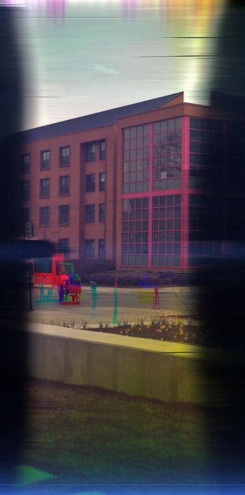
Three separate scans using a 25A red, 47 blue, and a combo X1+Y2 greenish filters. Added together in photoshop and auto-leveled, plus some addition saturation, and some highlight/shadow work.
The green is not a true tricolor green, it's more yellowish. I need to buy the 61 green to get better matching.
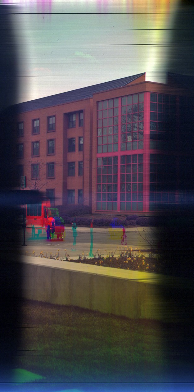
Three separate scans using a 25A red, 47 blue, and a combo X1+Y2 greenish filters. Added together in photoshop and auto-leveled, plus some addition saturation, and some highlight/shadow work.
The green is not a true tricolor green, it's more yellowish. I need to buy the 61 green to get better matching.
Friday, April 11, 2008
Adventures in Large Format Digital Scanning: Part 3
Click to enlarge any of these to the original size (the first image is actually only 50%).

An early image with the prototype cardboard camera. This image was auto-leveled, sharpened, and hue altered to attempt to match the original color out of the camera.
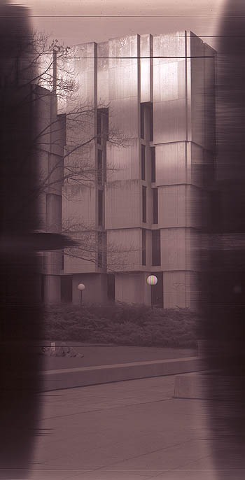
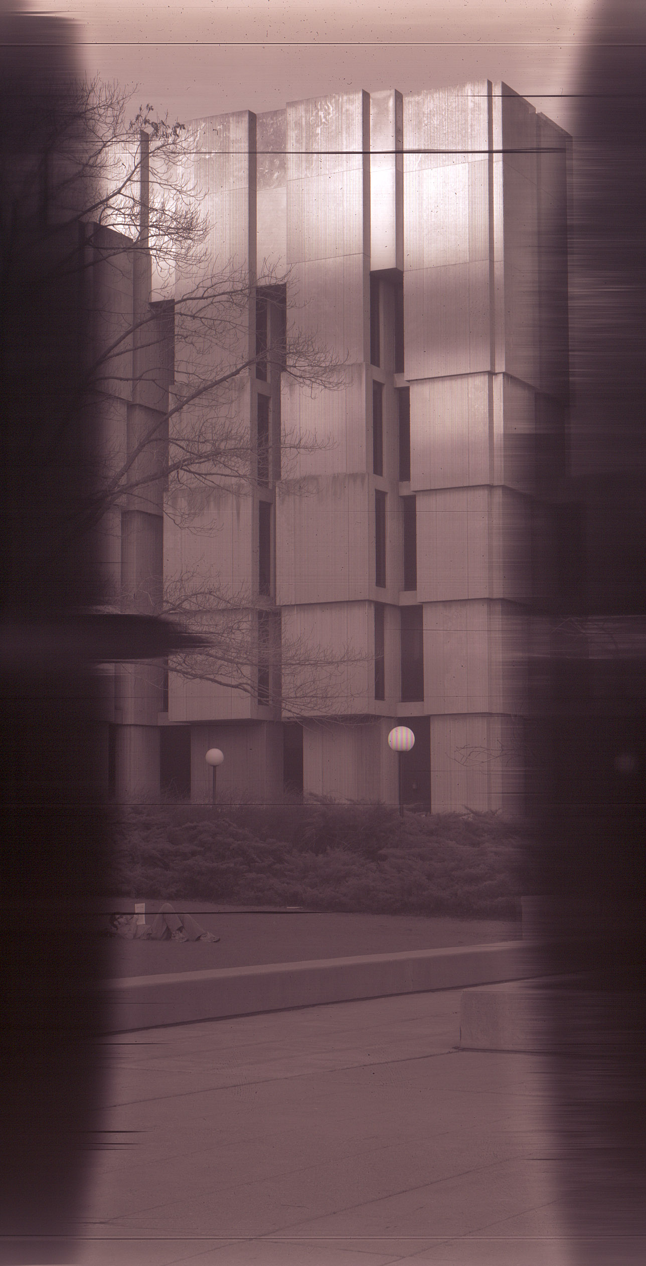
When outdoors with a small aperture all the dust on the scanner glass becomes visible, as seen in this and all further images in this post. I ended up cleaning it after this first trip outdoors.
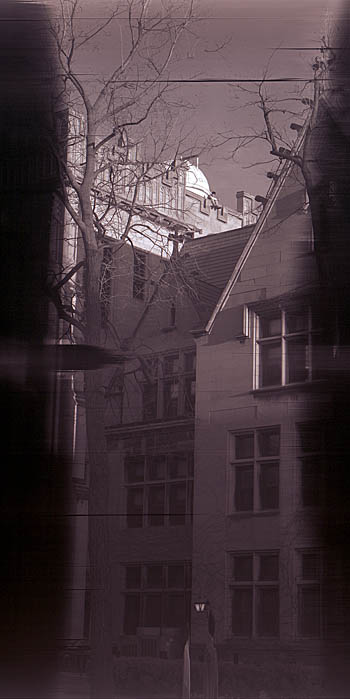
You can heavily sharpen the images out of the camera: this one is at 169%. I am still experimenting with basic things like focusing and apertures, so final sharpening levels are way in the future.
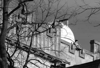
I made a second scan of Lui at 1200dpi, cropped, and cropped some more in post-processing. It looks soft on the original and I think 1200dpi might be interpolated (although Canon says 1200x2400dpi). It's also possible the focus was off.

An early image with the prototype cardboard camera. This image was auto-leveled, sharpened, and hue altered to attempt to match the original color out of the camera.
When outdoors with a small aperture all the dust on the scanner glass becomes visible, as seen in this and all further images in this post. I ended up cleaning it after this first trip outdoors.
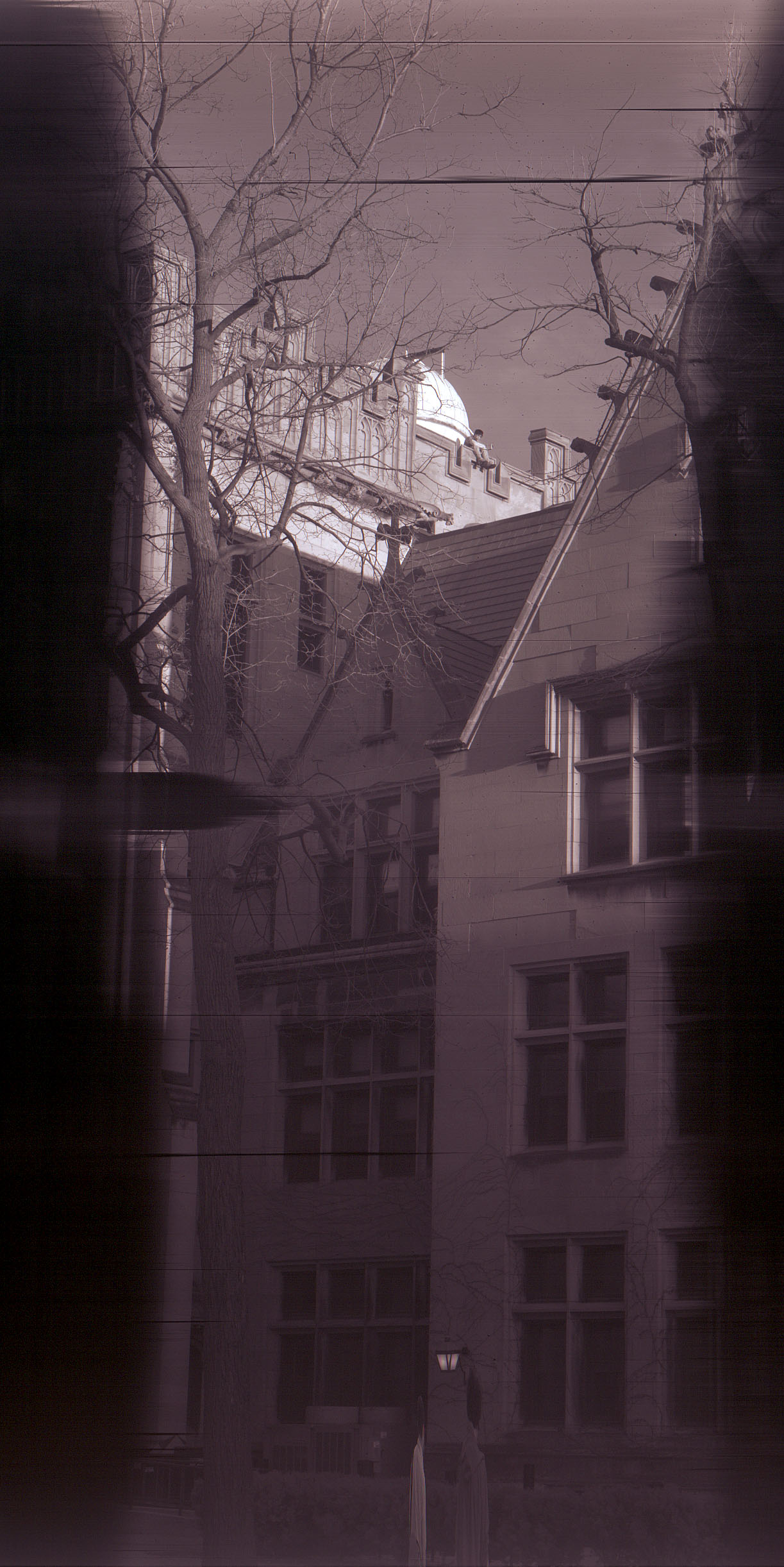
You can heavily sharpen the images out of the camera: this one is at 169%. I am still experimenting with basic things like focusing and apertures, so final sharpening levels are way in the future.
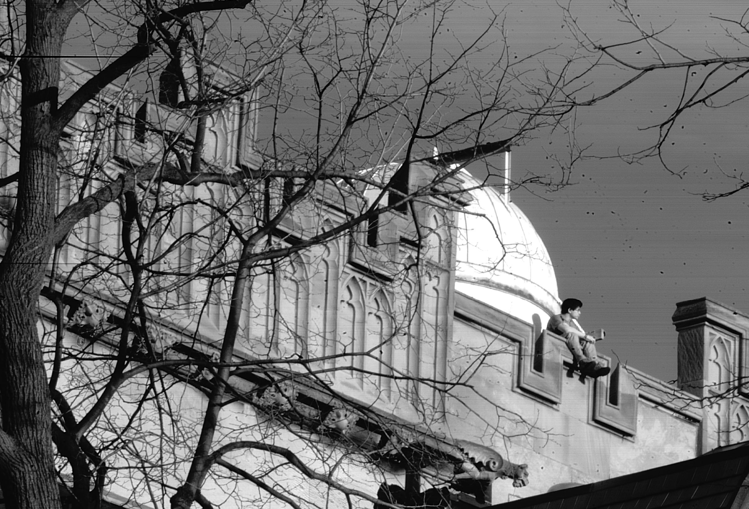
I made a second scan of Lui at 1200dpi, cropped, and cropped some more in post-processing. It looks soft on the original and I think 1200dpi might be interpolated (although Canon says 1200x2400dpi). It's also possible the focus was off.
Wednesday, April 09, 2008
Adventures in Large Format Digital Scanning: part 2
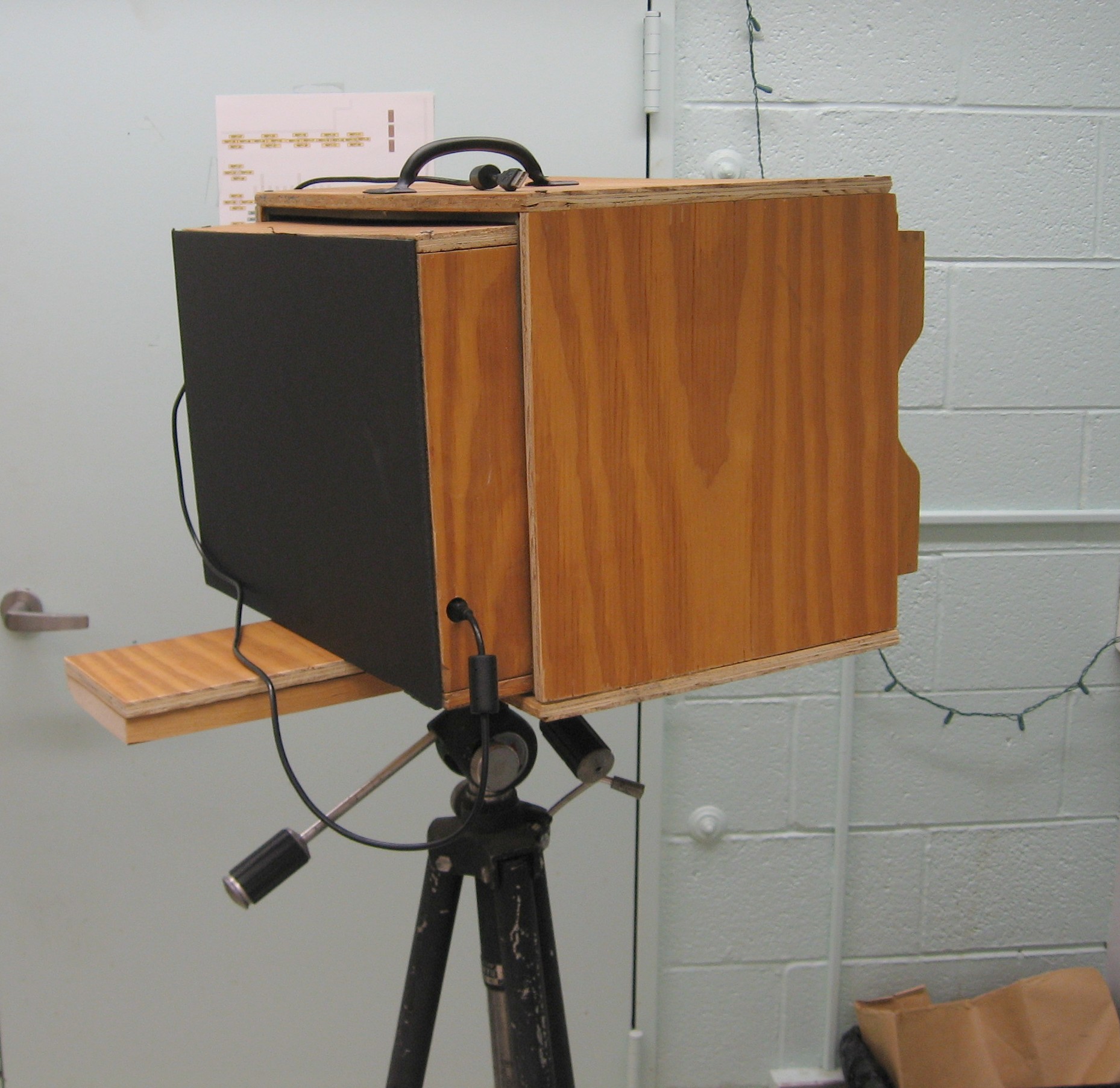
Some photos of the current iteration of the large format scanner camera. I built this over the past month after getting out of the mark I cardboard prototype phase.

The front of the camera holds a 8x10 format lens. It's mounted in a ring that attaches to a wooden inbox. The lens is a "Rapid Rectilinear", a symmetrical lens with four lenses in two groups around a stop. The lens type was invented in 1866 and was the predominant lens for about 50 years. My particular model lacks an iris and instead you insert thin metal sheets called Waterhouse stops into a slot on the lens to select an aperture. For the moment, I make the stops out of ordinary playing cards.
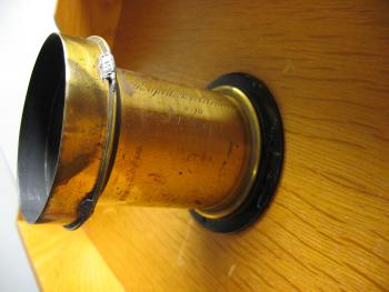
Both the lens and lens mounting ring were bought on Ebay.
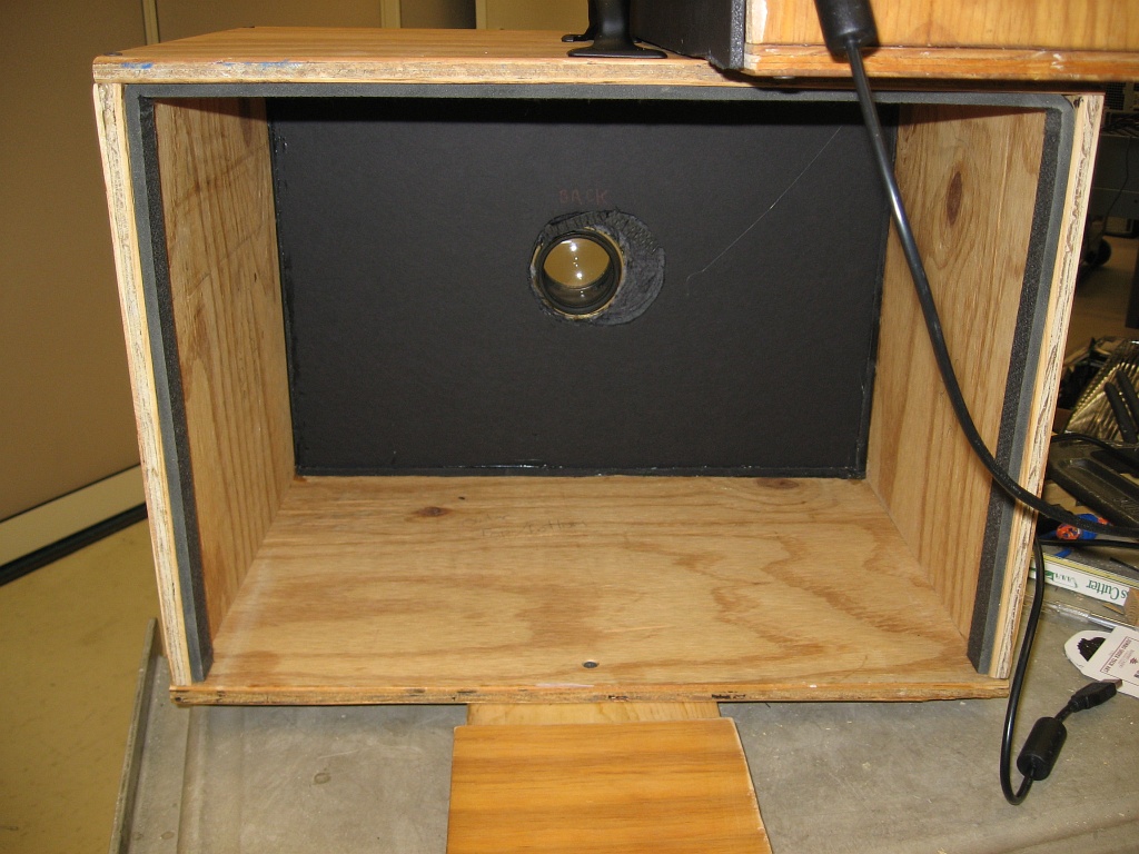
The camera is a sliding box camera: two boxes, one slightly smaller than the other, are slid to focus the camera. Major portions of the boxes are made out of 1/2-inch plywood. The front and back of the camera are black foam-core board. I used some weatherstripping to block light in between the inner and outer box. Thanks to Tod Olson for the plywood and cutting help.
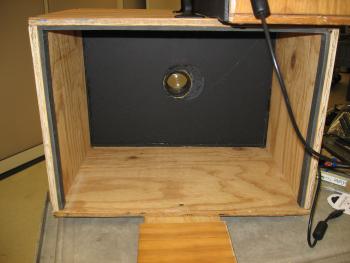
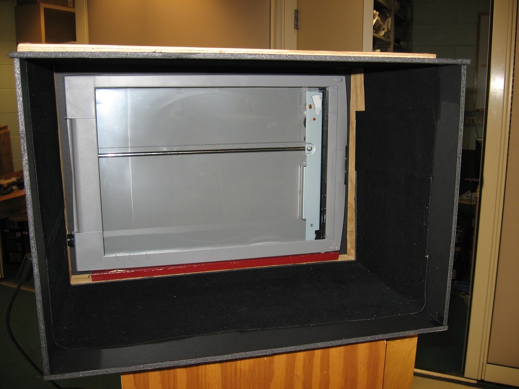
The Canon scanner sits at the back of the camera. The inside of the camera near the scanner is covered in self-adhesive black flocking paper from Protostar. Some additional foam-core board makes a light shield in front of this box when focusing close objects.
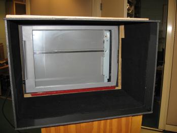
The large box and the front lens board are mounted on a 1" x 5" board, cut to about 24". A 1/4 x 20 tripod bushing is glued into a slightly depressed cut underneath. A small piece of 1/2-inch plywood at the back supports the inner box when focusing on close objects. The focusing range is from infinity to just under 4ft.
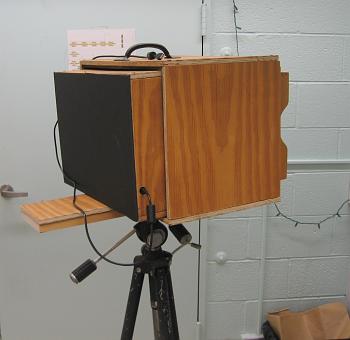
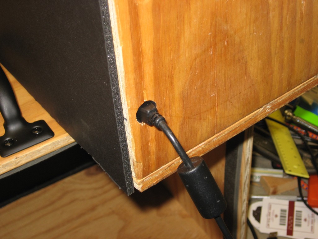
The scanner is powered via the USB connection.
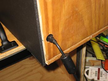
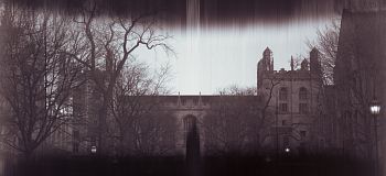
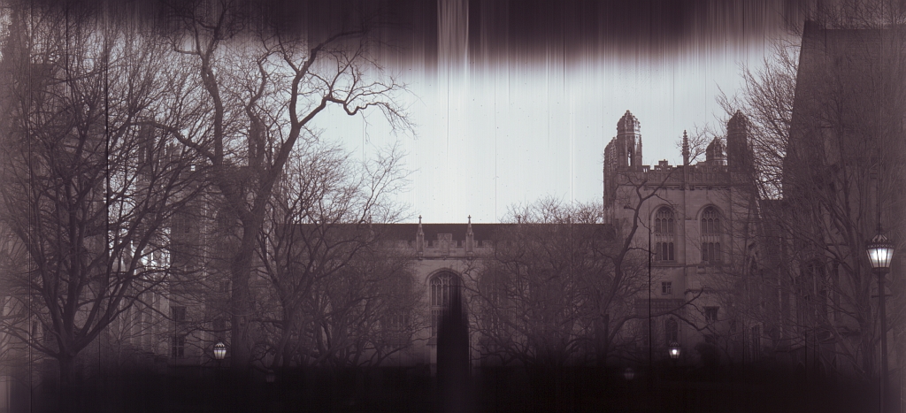
Here's an image out of the camera. I turned it on its side to get a better view of Harper. The only thing I did was sharpen it a touch: it can be sharpened much more. The vignetting is optical in the scanner and requires some additional surgery to the scanner before it allows me to scan the entire 8.5" x 11.7" area. This particular image I scanned at 300dpi.
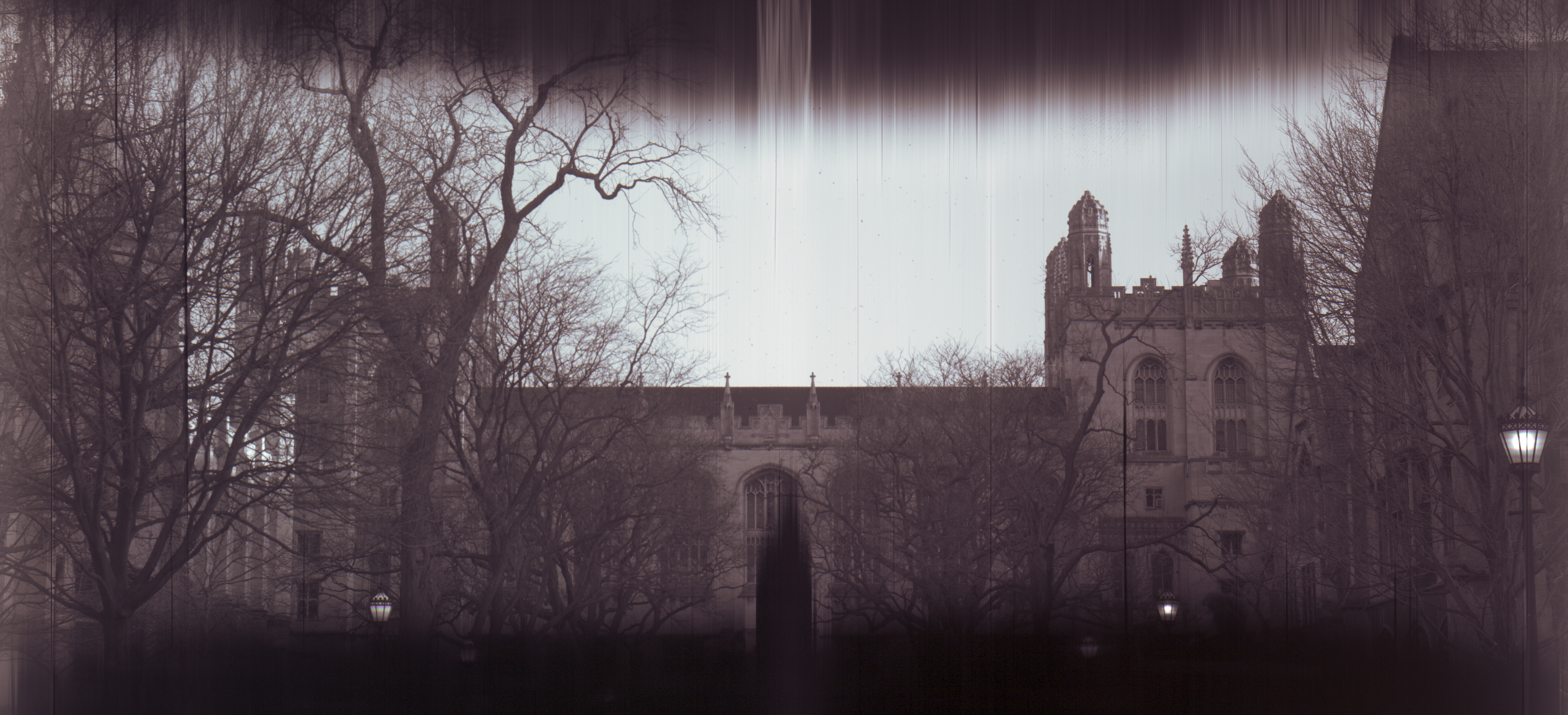
To view the image unaltered out of the camera, click here. It's 2532x1155.

The front of the camera holds a 8x10 format lens. It's mounted in a ring that attaches to a wooden inbox. The lens is a "Rapid Rectilinear", a symmetrical lens with four lenses in two groups around a stop. The lens type was invented in 1866 and was the predominant lens for about 50 years. My particular model lacks an iris and instead you insert thin metal sheets called Waterhouse stops into a slot on the lens to select an aperture. For the moment, I make the stops out of ordinary playing cards.
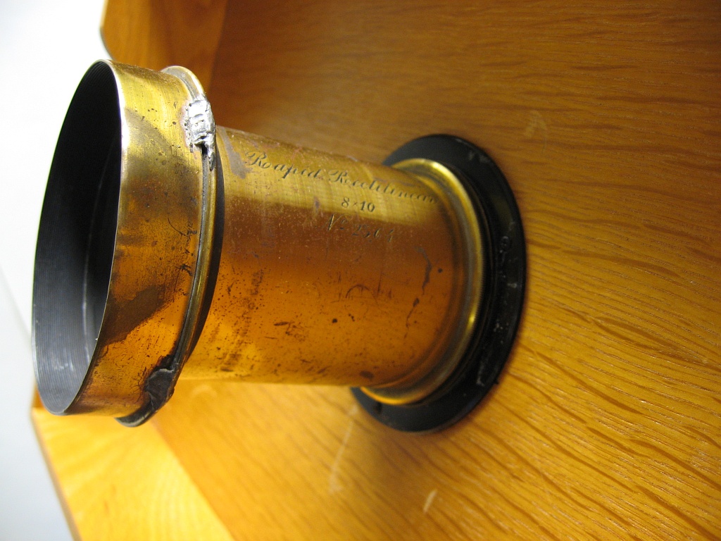
Both the lens and lens mounting ring were bought on Ebay.
The camera is a sliding box camera: two boxes, one slightly smaller than the other, are slid to focus the camera. Major portions of the boxes are made out of 1/2-inch plywood. The front and back of the camera are black foam-core board. I used some weatherstripping to block light in between the inner and outer box. Thanks to Tod Olson for the plywood and cutting help.
The Canon scanner sits at the back of the camera. The inside of the camera near the scanner is covered in self-adhesive black flocking paper from Protostar. Some additional foam-core board makes a light shield in front of this box when focusing close objects.
The large box and the front lens board are mounted on a 1" x 5" board, cut to about 24". A 1/4 x 20 tripod bushing is glued into a slightly depressed cut underneath. A small piece of 1/2-inch plywood at the back supports the inner box when focusing on close objects. The focusing range is from infinity to just under 4ft.
The scanner is powered via the USB connection.
Here's an image out of the camera. I turned it on its side to get a better view of Harper. The only thing I did was sharpen it a touch: it can be sharpened much more. The vignetting is optical in the scanner and requires some additional surgery to the scanner before it allows me to scan the entire 8.5" x 11.7" area. This particular image I scanned at 300dpi.
To view the image unaltered out of the camera, click here. It's 2532x1155.
Sunday, April 06, 2008
Adventures in Large Format Digital Scanning: part 1
Have you ever taken a magnifying glass in a darkened room and focused the scene outside on a wall? Or just focused the sun or a bright light?
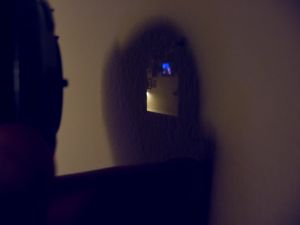
an image from a 50mm lens: the scene from the other room.
An even simpler optical system is the pinhole: Light rays are constrained in that there is one angle, and one angle only, that they can go through the pinhole, making an always in-focus optical system. There are pinhole systems everywhere: just go under a tree. All those round discs of light? Real images of the Sun. Most people don't notice until the Sun is eclipsed by the Moon, when those round discs turn into a thousand crescents.
Going back to the image formed from a real lens. Can you see if you replaced the wall with a piece of film, you've made yourself a camera? What if you put a CCD there? (That's the "film" of digital).
Now take a flatbed scanner. Those devices image just what's put right in contact with the glass on top of them. A piece of paper, a print, a film negative, etc. What if we put a flatbed scanner in the focal plane of the lens from above? If everything went right, we'd be scanning the image produced by the lens.
This is the technique used by a number of early medium format and current large format digital backs. For instance, see this Seitz scanning back or the range of scanning backs at BetterLight.
Now these are nice and all, but I don't have tens of thousands of dollars nor a 4x5 camera to stick a digital back on. So I decided to build one. This post has been sitting for quite some time with me wondering exactly how to start describing this project. My hand has been forced though, as yesterday I took my prototype outside for the first time and people starting asking questions.
So, here's an image from yesterday. Ignore the defects. The original is 1268x2552. I can quadruple that resolution at the moment, but didn't in this particular image.
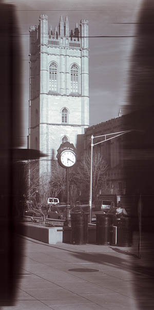
Reynolds Club at 300dpi, smallish aperture, no IR block. Slight levels adjustment, unsharp mask. Click to enlarge.
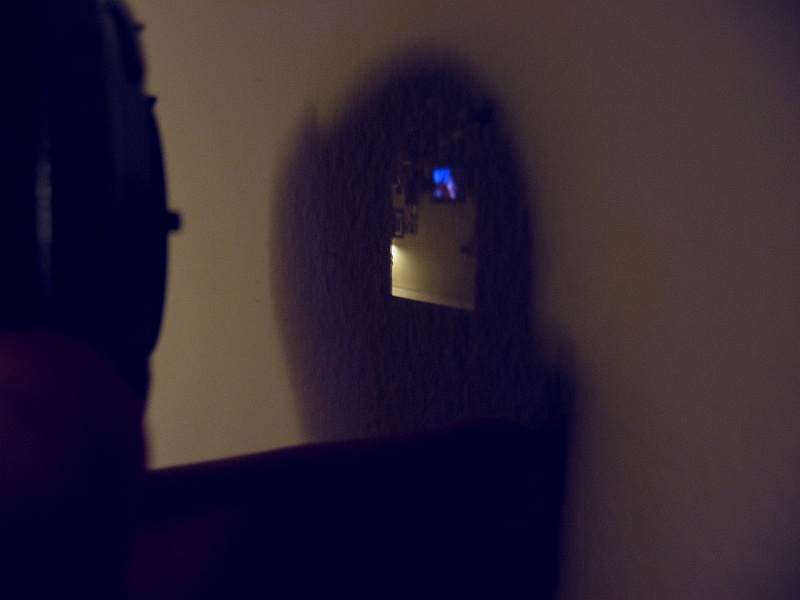
an image from a 50mm lens: the scene from the other room.
An even simpler optical system is the pinhole: Light rays are constrained in that there is one angle, and one angle only, that they can go through the pinhole, making an always in-focus optical system. There are pinhole systems everywhere: just go under a tree. All those round discs of light? Real images of the Sun. Most people don't notice until the Sun is eclipsed by the Moon, when those round discs turn into a thousand crescents.
Going back to the image formed from a real lens. Can you see if you replaced the wall with a piece of film, you've made yourself a camera? What if you put a CCD there? (That's the "film" of digital).
Now take a flatbed scanner. Those devices image just what's put right in contact with the glass on top of them. A piece of paper, a print, a film negative, etc. What if we put a flatbed scanner in the focal plane of the lens from above? If everything went right, we'd be scanning the image produced by the lens.
This is the technique used by a number of early medium format and current large format digital backs. For instance, see this Seitz scanning back or the range of scanning backs at BetterLight.
Now these are nice and all, but I don't have tens of thousands of dollars nor a 4x5 camera to stick a digital back on. So I decided to build one. This post has been sitting for quite some time with me wondering exactly how to start describing this project. My hand has been forced though, as yesterday I took my prototype outside for the first time and people starting asking questions.
So, here's an image from yesterday. Ignore the defects. The original is 1268x2552. I can quadruple that resolution at the moment, but didn't in this particular image.
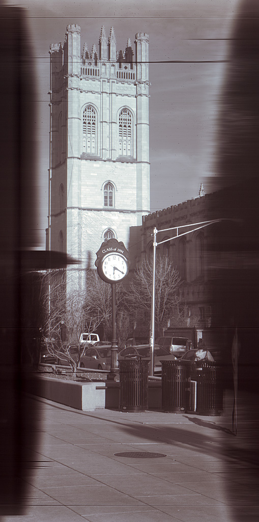
Reynolds Club at 300dpi, smallish aperture, no IR block. Slight levels adjustment, unsharp mask. Click to enlarge.
Subscribe to:
Posts (Atom)