My long-suffering Geiger counter is now back up and running.
http://www.lib.uchicago.edu/~dean/float.htm.
Now, as has been pointed out, this particular instance of this experiment is really an experiment, and is run only by me, for only experimental purposes. It doesn't represent any opinion or endorsement or opinion of any entity, whether the University of Chicago Library or the University or anything else. It is not a service. It represents nothing, is not calibrated, and should not be relied upon by anyone for anything. Don't email or call anyone but myself about it.
This instance is located in my office on the A-level of the Regenstein Library, the first basement level of a six-story building. The levels average about 8 microrads/hr here. Outside at Ryerson Physical Laboratory on the fifth floor, levels average to about 12 microrads/hr, which indicate the shielding provided by the Regenstein against the cosmic ray flux.
The problem I've been having with this counter was with the associated AW-SRAD software, which runs under DOS, doesn't appear to support virtual COM ports above COM4. On my Windows XP PC I had installed an Arduino which offered a similar USB Serial converter and I theorize at some point there was a conflict and the Geiger counter with its FTDI USB to serial converter took a high COM port at COM5. After removing the Arduino, I then disabled the real serial port at COM1 and forced via Device Manager->Ports->USB Serial Ports the port to go to COM1.
Showing posts with label electronics. Show all posts
Showing posts with label electronics. Show all posts
Wednesday, March 16, 2011
Thursday, March 10, 2011
Audio stereo isolation circuit diagram
Two years I made an audio stereo isolation transformer, suitable for getting rid of ground loop problems in a line-level audio connection. Here's a simple circuit diagram that attempts to match the colors of the physical device.

http://www2.lib.uchicago.edu/~dean/blog/isolation-transformer.dsn
Circuit diagram for TinyCAD.

http://www2.lib.uchicago.edu/~dean/blog/isolation-transformer.dsn
Circuit diagram for TinyCAD.
Thursday, September 09, 2010
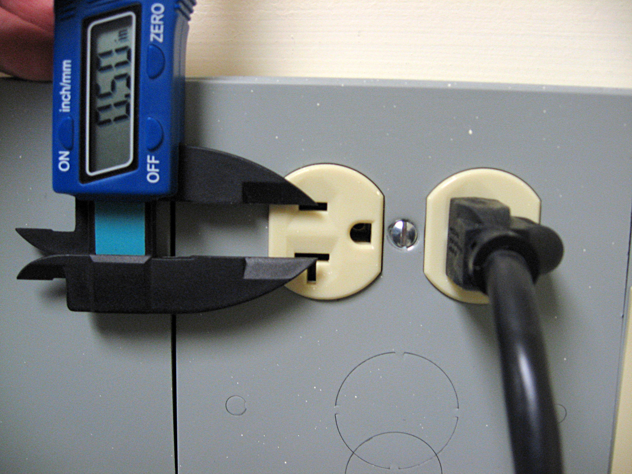
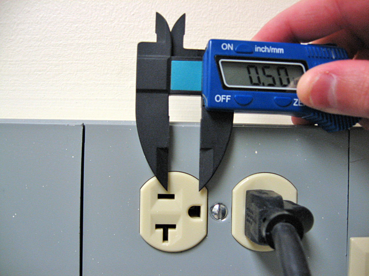
Notable: the size of the standard AC outlet
Did you know the distance between the center of the slots in the 120V standard AC outlet is exactly 1/2 inch? And so is the distance between the center of those and the center of the ground pin. 0.5". All of this only came out after I bought an inexpensive digital caliper and started measuring everything I could get my hands on.


Wednesday, January 27, 2010
Joule Thief: a simple DC voltage booster
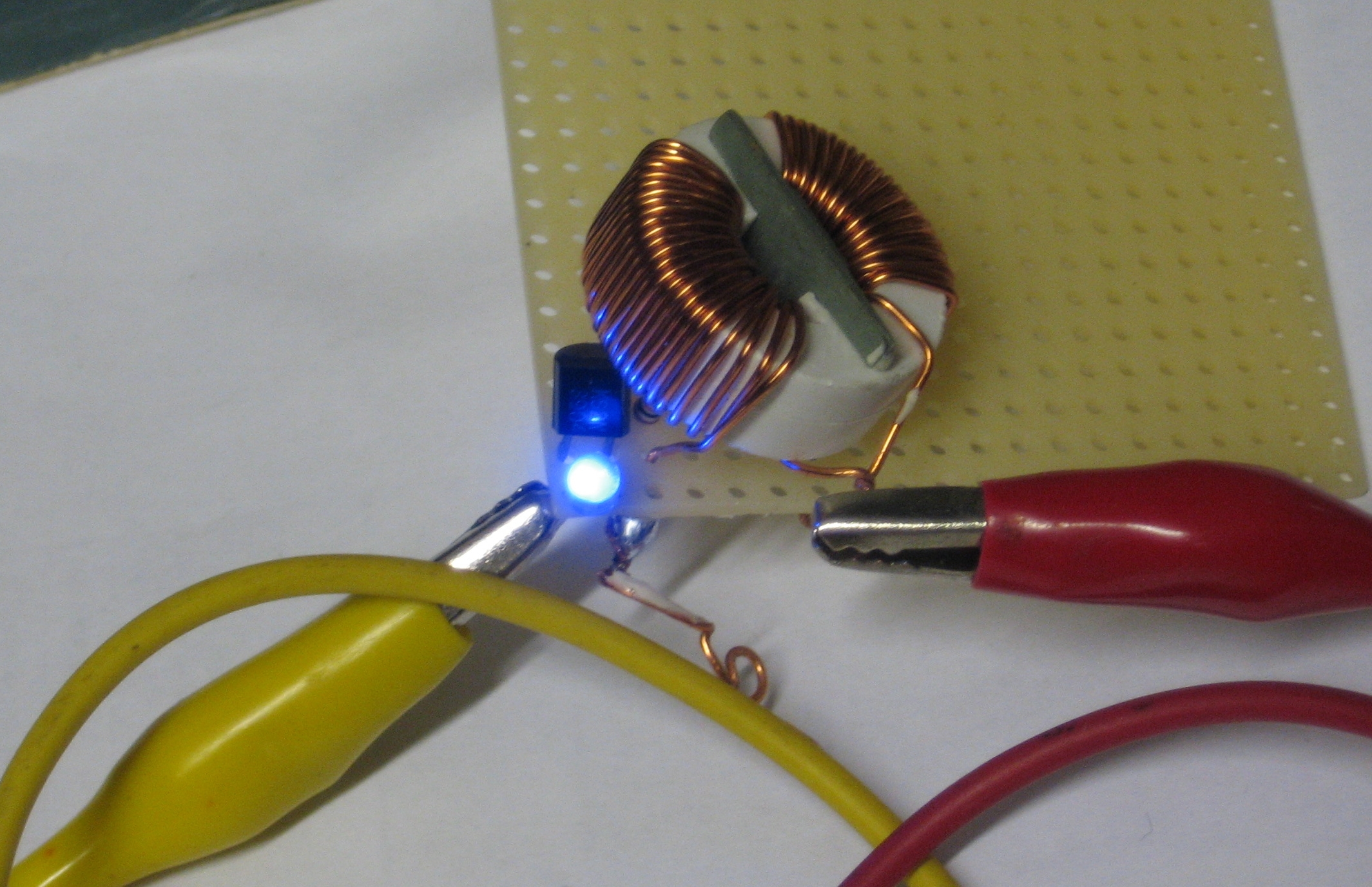
A joule thief circuit lit from a 0.5V AAA battery. Click to enlarge.
A Joule thief is a simple circuit that acts as a DC to DC booster, raising a supply voltage by several volts. In this iteration it uses the exhausted voltage of a alkaline battery and boosts it enough to light a blue LED that requires 2.8V to light. With an otherwise dead 0.5V AAA battery, it will light a blue LED and run for days, using (at the moment) just under 2mA of current. It's much much dimmer than using a fresh battery or running the LED with a proper current through it. Giving the Joule thief circuit 3V from two fresh batteries pulls 75mA through the LED, making it very, very bright and probably short-lived.
A schematic is below. The circuit works like this: When first turned on, current flows into the inductor and produces a magnetic field in the toroid. While this is happening, no voltage appears at the base of the transistor, so the transistor remains off. The LED sees at first no voltage and while the inductor fills up, it only sees a maximum voltage of the battery, which is not enough to pass the diode. Once the inductor is charged, the battery voltage appears at the base of the transistor, turning it on. This allows the right side of the inductor to want to dump the energy it has stored in its magnetic field as quickly as possible, and this gives us a high-voltage that appears across the inductor. When that voltage exceeds 2.8V the LED turns on and lights up until the voltage drops below, triggering the sequence to begin again. I measured the frequency of the on/off oscillation and it seems to run at about 34kHz; the multimeter said between 68 and 72kHz but a radio showed there was 34kHz signal as well, which I assume was the fundamental (and the 68kHz one a harmonic). It did change in frequency a bit while on.
 Bre Pettis/Windell Oskay
Thursday, September 24, 2009
Geiger counter current draw
This circuit connected to my geiger counter uses on average 80uA-- that's 0.08mA. On a click, it will bump up to 0.1mA. On startup just for a second it uses 3mA. At those rates, and with a standard 9V battery (at 650mAh), it would run about 9 months continously.
Monday, June 08, 2009
Audio isolation transformer
I used to record audio off my Tivo on my desktop computer--but when I had the cable TV connected, I would get a loud hum. The reason for this is related to the idea of "ground" in electrical systems, which are used as a reference point for zero voltage and/or safety purposes. The kicker was the cable TV cable offered a different path to ground compared to the PC's ground.
For consumer generic audio connections, the audio signal (a varying AC voltage of about one volt) is compared to the ground of the system. Hence the two connectors on an RCA connector, signal and ground, or three connectors on a stereo jack: left, right, and ground. If your ground happens to be varying up and down at 60 times a second (because it's not a good ground, for instance), you will also get that hum on your output.
For some professional audio systems, the reference ground is brought with the signal, so you have three connections for any channel. When both the signal and ground vary up and down in sync, it's easy to subtract the pickup noise and have a clean signal.
In simple, single systems, either approach works fine. The problem is when you start interconnecting equipment.
I made a stereo isolation audio transformer to solve this problem. The left and right channels enter a 1:1 600ohm audio transformer, which transmits the audio signal (which is AC) but blocks any DC connection. This prevents ground loops and currents between the two devices. I got the two transformers from old modems. One of the jacks is a fancy panel mount, the other is from an old sound card, and this old one is actually needed, because it is plastic, isolating it from the case, which is connected to the ground of the panel mount jack. Of course, I put everything in an Altoids tin.
I suppose it would also help if I put some ferrite on the inputs to also reduce RFI/EMI problems, but I haven't yet. Just having this device between a shortwave radio and a PC has reduced interference pickup quite a bit.
You can see more photos of the build at http://www.flickr.com/photos/dwarmstr/sets/72157604679420753/. Essentially, 1. Measure and Mark your holes. 2. Make a small punch to keep drill centered. 3. Drill a pilot hole, then the right size. 4. Solder the connections. I used a multimeter to figure out which connection was which on the transformers. 5. Hot glue for stability.
Parts cost: about $2.50 for the 3.5mm stereo panel mount. Everything else I scrounged for from old parts, not counting my time. Here's the equivalent commercial product at $32: http://www.amazon.com/3-5mm-Stereo-Audio-Isolation-Transformer/dp/B001GUS7EO. I do enjoy the look of that commercial case.
Sunday, January 25, 2009
Microwave meter videos
I made a few videos of the simple microwave / 2.4GHz meter dealing with work office's microwave oven--woe be unto whomever hangs around the hinge.
The first is a full examination of the space of the microwave oven, and is entirely inappropriate for those with short attention spans (stick to the second video, you).
This one is a short proof the detection is when the microwave oven is busily heating my hot water for tea.
The other amazing news is there is a very strong microwave signal that the northwest corner of the roof of Ryerson intercepts that appears to be coming from either the Admin building or the hospital: it strongly peaks in the southwest direction, almost pegs the meter on the 200mV scale, and when I added a headphone to the meter I could audibly hear some sort of signal that reminded me of a TV video sync noise.
What is this signal? Am I hearing a horizontal sync? Or is there some other signal that has a repetitive sync noise that runs at 12-18 kilohertz?
Wednesday, December 17, 2008
a very simple 2.4GHz meter

I built a very simple meter that reads the strength of radio energy in its vicinity, without amplification or anything fancy. It picks up radio waves roughly around 1 to 3 gigahertz. It does very well in detecting cell phones, microwave ovens, and wireless access points.
On a simple level, the antenna converts radio waves into an electrical AC voltage, which is then converted by the germanium diode into a pulsing DC voltage. A capacitor stores the pulses and smooths out the pulsing and leaves a very small DC voltage, which is measured directly at a tiny multimeter I picked up at American Science and Surplus. I set the meter to DC voltage, 200mV scale.
The biquad antenna is sensitive to vertically polarized waves and slightly directional as well. A lot of designs also stick a ground plane behind it to increase the directionality, but I was looking for more of a field strength probe, rather than having an antenna that got me the most gain. It's a trade-off since the detector is so simple and without amplification, but that's what you get.

What can we measure with this meter? My standard test suite for gigahertz-ish radio frequencies is delinquent*, so all I can think of is cell phones, microwave ovens, and wireless networking. I found that the office microwave oven puts much more energy out at the hinge side of the door and a fan vent on the side than it does the meshed window. It can saturate the meter at the 200mV scale (when right next to the fan vent). Cell phones periodically check in with their towers (you can also tell this with a set of computer speakers anywhere near a GSM phone). They also do put out a bit of gigahertz radiation; I can detect them sending text messages from about six feet away and more when talking--they can also reach 200mV. Wireless 802.11b and g networks are actually pretty low-power in the scheme of things--they hard to see except close-up until they are transmitting data; then I can detect them six or so feet away. During idle they emit a "beacon" 10 times a second. The wifi antennas are also a good source for checking the polarization of the biquad--I get nearly nothing from them if I rotate the receiving antenna 90 degrees.

Outside the signal level varies greatly. There is a pervasive field which is presumably cellular networks and the addition of all the 802.11b/g/n networks. On the University of Chicago campus near the Regenstein Library the average strength varies from 0.2mV to 0.6mV, with a couple of spikes to 1.0mV. There are also areas of much stronger than ambient. For instance, outside of the Medici on 57th street the average field strength is 2-3mV and peaks at moments at 8mV. There are cellular tower antennas on a school across the street; so it seems likely the area is getting a particular sector of the tower.
I used this Field Strength Meter for 2.4 Ghz Wireless LAN as the excellent template for the project. For my version I used a standard 1N34A germanium diode--this is a more sensitive diode, and turns on at 0.3V instead of 0.6V like a standard silicon diode. I painted the diode black, as the diode proved to be photo-sensitive (all PN junctions are light-sensitive, and ones in transparent glass tubes even more so). Also, I didn't tune the capacitance at all. I then ran two wires to the inside plugs and drilled a hole in the case and hot-glued the antenna to the front of the meter. It's nice and compact, although the GP23A 12V battery in it doesn't last very long.
I could see easy modifications of this system, putting a simple FET amplifier or such to increase the meter response. If I use one of the inexpensive multimeters from Harbor Freight I might have enough room for a prebuilt circuit and a more directional antenna. I'd also like to see if I can pick up both aviation and weather radars with such a simple system. Maybe I should make a Sardine Can antenna?
*delinquent is also a synonym for nonexistent.
Thursday, August 14, 2008
When in doubt, blame the instrument: It wasn't the lightning.
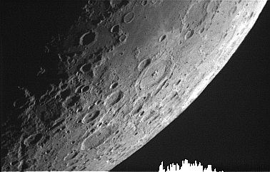
The WGN Weather blog shows a video from Bucktown of the intense thunderstorm of August 6th here: http://blogs.trb.com/news/weather/weblog/wgnweather/2008/08/incredible_viewer_video.html, but they claim that the nearby lightning strike at the end of the video actually produced arcing close to the camera. That wasn't the case. The "arcing" is actually an artifact of the CCD sensor in the video camera. To understand what's going on, you'll have to deal a little bit with the physics of CCDs. In silicon, incoming photons will excite electrons out of a lower energy state and into the "conduction" band where it can then migrate through the material. You can call this liberating the electron. In a CCD control voltages create zones where these freed electrons are trapped in the silicon until they are moved out and measured. Those zones are best known as pixels. Depending on the type of CCD, when the exposure is over, the electrons are moved pixel by pixel in columns to be read.

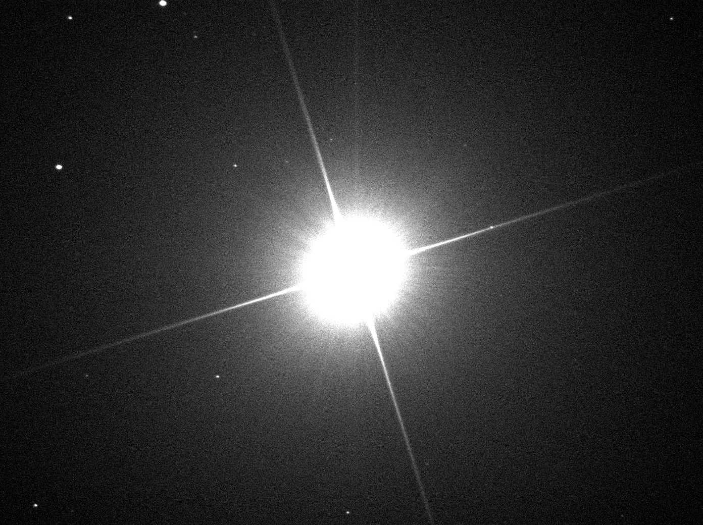
Intensely bright sources of light will produce so many electrons that they will overwhelm the control voltage and flood out of the pixel and into the surrounding pixels and circuitry, producing spurious effects. You've probably seen these effects -- it starts showing up at 1:57 in the Yeah Yeah Yeahs video for Maps for example, or in the SOHO image above (it's Venus doing the blooming).
In this case the electrons flow out and down the columns that the electrons would normally be read. The Sun is a great source of column bleeding in a lot of videos online: see this one, for instance. Or bright stars--here is a weak version (it's the faint vertical column, not the diagonal streaks):

Since it's difficult to control all the sources of light in any possible photo scene, the CCD manufacturers have ways of trying to mitigate the overflowing electrons. One technique is to put drainage canals around the pixels and dump the electrons. This is good, but the extra space for drainage costs you some light sensitivity and light measuring accuracy.

Another problem can develop while you are moving the electrons off the CCD to be measured--if you have a shutterless camera, then light is still hitting all the pixels and can still cause overflow problems. One technique (used a lot for video cameras, at least in the old days) is to make the CCD twice as big with half of the chip covered up. At the end of the exposure you quickly move the electrons in the lit part over to the dark part and then leisurely read them out. This helps, but you can still have those overflowing electrons come down into your dark area.
So, in the lightning video, you can see that the extremely bright strike produces too many electrons in the CCD of the camera, and they flow 1. into the dark frame-transfer area and 2. down the columns (the vertical bleeds).
You can see at least one of these effects in some of the other strikes in the video.

Intensely bright sources of light will produce so many electrons that they will overwhelm the control voltage and flood out of the pixel and into the surrounding pixels and circuitry, producing spurious effects. You've probably seen these effects -- it starts showing up at 1:57 in the Yeah Yeah Yeahs video for Maps for example, or in the SOHO image above (it's Venus doing the blooming).
In this case the electrons flow out and down the columns that the electrons would normally be read. The Sun is a great source of column bleeding in a lot of videos online: see this one, for instance. Or bright stars--here is a weak version (it's the faint vertical column, not the diagonal streaks):
Since it's difficult to control all the sources of light in any possible photo scene, the CCD manufacturers have ways of trying to mitigate the overflowing electrons. One technique is to put drainage canals around the pixels and dump the electrons. This is good, but the extra space for drainage costs you some light sensitivity and light measuring accuracy.
Another problem can develop while you are moving the electrons off the CCD to be measured--if you have a shutterless camera, then light is still hitting all the pixels and can still cause overflow problems. One technique (used a lot for video cameras, at least in the old days) is to make the CCD twice as big with half of the chip covered up. At the end of the exposure you quickly move the electrons in the lit part over to the dark part and then leisurely read them out. This helps, but you can still have those overflowing electrons come down into your dark area.
So, in the lightning video, you can see that the extremely bright strike produces too many electrons in the CCD of the camera, and they flow 1. into the dark frame-transfer area and 2. down the columns (the vertical bleeds).
You can see at least one of these effects in some of the other strikes in the video.
Friday, June 06, 2008
Updates: Tesla coil and light bulb
Updates.
I tried to help Igor out on his Tesla coil. It's a traditional spark-gap variety coil. The problem was the secondary kept arcing over to the primary or elsewhere from near the bottom, nowhere near the top, and we didn't see any streamers or such from the top. Nothing we tried would insulate the primary from the secondary--styrofoam, electrical tape, plastic cups. When we changed where we connected to the primary the sparks would change their behavior--sometimes we would get a single spark or sometimes we would get what we think was called "racing sparks"--the ones that jump a few inches on the secondary. Also we tried grounding, although we were up on a third story. All this, plus the fun of a spark gap that literally was too loud to operate. Bang-bang-bang! We need to enclose the spark gap in something to absorb the sound, but to do that would mean we'd also have to set up an air flow via a fan to break the arc. No photos of this work.
The other is a revisit to a Scav Hunt item, a homemade light bulb. This was a success on our part. We used a 0.5mm mechanical pencil lead, connected it to a pair of 6V latern batteries wired in series, giving 12V. The filament was enclosed in a Snapple bottle with wire passed through a hole in the cap sealed with hot glue. To remove oxygen in the air we lit a match or two in the bottle until it went out and sealed quickly. This bulb had a nice ruddy glow to it. We only ran it for thirty seconds or so before it was passed on for the judges to see. I don't know where it is now, so I decided to make another one. The basics were the same except for the power source. I used a 15V AC 1A power supply. I put the filament in a Starbucks glass container that I had worries about being airtight enough. This time it lit nicely, but within ten seconds one side of the graphite became brighter. A post-mortem showed it got brighter because the lead got narrower, and more power was dissipated there, increasing the erosion. It got brighter and brighter and then narrowed to nothing, when it broke.

Graphite filament assembly

Light bulb lit

Lightbulb movie -- Click to play -- sorry for the poor aspect ratio
I tried to help Igor out on his Tesla coil. It's a traditional spark-gap variety coil. The problem was the secondary kept arcing over to the primary or elsewhere from near the bottom, nowhere near the top, and we didn't see any streamers or such from the top. Nothing we tried would insulate the primary from the secondary--styrofoam, electrical tape, plastic cups. When we changed where we connected to the primary the sparks would change their behavior--sometimes we would get a single spark or sometimes we would get what we think was called "racing sparks"--the ones that jump a few inches on the secondary. Also we tried grounding, although we were up on a third story. All this, plus the fun of a spark gap that literally was too loud to operate. Bang-bang-bang! We need to enclose the spark gap in something to absorb the sound, but to do that would mean we'd also have to set up an air flow via a fan to break the arc. No photos of this work.
The other is a revisit to a Scav Hunt item, a homemade light bulb. This was a success on our part. We used a 0.5mm mechanical pencil lead, connected it to a pair of 6V latern batteries wired in series, giving 12V. The filament was enclosed in a Snapple bottle with wire passed through a hole in the cap sealed with hot glue. To remove oxygen in the air we lit a match or two in the bottle until it went out and sealed quickly. This bulb had a nice ruddy glow to it. We only ran it for thirty seconds or so before it was passed on for the judges to see. I don't know where it is now, so I decided to make another one. The basics were the same except for the power source. I used a 15V AC 1A power supply. I put the filament in a Starbucks glass container that I had worries about being airtight enough. This time it lit nicely, but within ten seconds one side of the graphite became brighter. A post-mortem showed it got brighter because the lead got narrower, and more power was dissipated there, increasing the erosion. It got brighter and brighter and then narrowed to nothing, when it broke.

Graphite filament assembly

Light bulb lit
Lightbulb movie -- Click to play -- sorry for the poor aspect ratio
Wednesday, January 16, 2008
New star in a box
I received my latest box of goodies from Jameco, and in it was a particular weakness of mine.

I'm a sucker for the latest and greatest LEDs. This particular white LED is named "Piranha" by the manufacturer. In the picture I am running it at half-brightness.

Slightly underexposed to highlight the brightness

I'm a sucker for the latest and greatest LEDs. This particular white LED is named "Piranha" by the manufacturer. In the picture I am running it at half-brightness.
Slightly underexposed to highlight the brightness
Friday, January 11, 2008
Compact Fluorescents
Compact fluorescent lighting is a hot topic in the media right now. Repeated utility and environmental group campaigns have encouraged people to switch to them, and the Energy Independence and Security Act of 2007 will phase out the sale of incandescents in 2012. Economically speaking, there are real incentives for consumers to switch to them. But... people who have done so often come right back to incandescents. Why is that?
1. Quantity of light. CF manufacturers are blatantly over-reporting the luminosity of the CFs. This will probably not be resolved until a lawsuit occurs over the false advertising. To get an equivalent amount of light I always recommend getting the CFL that is a step-up: so if you are replacing a 60W incandescent, buy a "75W" CF. You'll be much happier, and don't fret the increase in energy use, since you are still using less energy than before (60W vs 20W for a "75W" CF), it's still a win.
2. Quality of light. This is the most legitimate complaint, and most of it stems from failure of manufacturers to label the color temperature of their bulbs. For most consumer applications, getting the color to match tungsten (2700K) is critical for acceptance. Some of the cheaper CFs have poor color rendition: they are too pink or too green and it turns off people. This is the fault of using the wrong phosphor blends. Take a gander at this quote from yesterday's NYTimes article on CFs:
Get the right color for your application. I use GE 6500K daylight bulbs during the day to completely match outside light--you would be hard pressed to figure out if the light from the other room was from a window or the bulb. I also have some old tube "full-spectrum" fluorescents to wake up to in the morning in my bedroom. Again, these have fantastic matching color rendition to daylight.
For nighttime, it's best to limit your exposure to blue light, as it disrupts the production of melatonin and hence your sleepiness. I switch to tungsten matching lights at night as much as possible. For matching incandescents, both the n:vision soft white and GE series match the color. The n:vision lights instantaneously, whereas the the GE takes too long to light (and has other objections below).
3. Noise. A false objection is the claim that compact fluorescents buzz like old magnetic ballast fluorescent tubes. This is just wrong--CFs haven't used magnetic ballasts for a long time. Electronic ballasts, as used in CFs, can make noise if components in them aren't physically attached as well as they can be, and if certain cheaper circuits are used. The fundamental switching frequencies are ultrasonic, so you can't hear the old buzz that magnetics do. But with the design issues mentioned you can have a variety of whines and higher frequency buzzes.
4. Time to light
Many CF bulbs take a delay to light. This is annoying and a common complaint for many brands of bulbs. I've found that GE's Soft White 20W(75W) has a 1/2 second light time that drives me insane.
In addition, every CF I've ever owned takes time to warm to full brightness. I don't mind a short delay. I've had no problem with the the warm-up time, but in hotels I've seen lights that have taken literally minutes to light up to full brightness.
5. Short lifetimes
A lot of people have reported the CFs aren't lasting as long as claimed. I can believe this, especially if they bought by price. The compact fluorescents also are very intolerant of cycling--don't use them in closets and places you don't need the lights on for hours at a time. The lights are also sensitive to overheating--so don't stick them in unventilated fixtures, or recessed ceiling cans, or in general any upside-down fixture.
Now for long life. In 1991 or so I bought a very early CF. It was underpowered--I think it's a 7W. I used it for a few years and then went to college. It's still sitting in my old room at my parent's place, and I use it whenever I visit. Granted, this means it doesn't have many hours on it, but that CF bulb is older than many people I know.
My own specific recommendations are to get N:Vision soft white CFs for general use. I can say they are as close to an incandescent as I've seen in CFs.
I built an awesome "halogen torchiere killer" that I'll describe in another post.
In the living room, for example, where there are four recessed lights along one wall, Mr. Chipman tested six dimmable bulbs and determined that one made by Greenlite with the same hue as incandescents worked best in certain spots, attractively lighting an exposed brick wall and maple bookshelves. A Satco brand bulb with a slightly whiter hue made a limestone-tiled fireplace in the middle of the wall look best, so he installed one above it. Mr. Chipman’s wife, Liz Diamond, 53, a theater director who considers herself even more particular about aesthetics than her husband, said investing time in trying multiple bulbs made a big difference. “There was one bulb that made the limestone look really freaky, ugly and moldy,” she said, but the Satco bulb now in place makes the space look “fabulous.” “I was amazed at how much variation there was, but you can really get a color that you like,” she said. Mr. Chipman agreed. “You really have to experiment with different bulbs to find the ones that work for you,” he said. “But they exist.”
Get the right color for your application. I use GE 6500K daylight bulbs during the day to completely match outside light--you would be hard pressed to figure out if the light from the other room was from a window or the bulb. I also have some old tube "full-spectrum" fluorescents to wake up to in the morning in my bedroom. Again, these have fantastic matching color rendition to daylight.
For nighttime, it's best to limit your exposure to blue light, as it disrupts the production of melatonin and hence your sleepiness. I switch to tungsten matching lights at night as much as possible. For matching incandescents, both the n:vision soft white and GE series match the color. The n:vision lights instantaneously, whereas the the GE takes too long to light (and has other objections below).
Many CF bulbs take a delay to light. This is annoying and a common complaint for many brands of bulbs. I've found that GE's Soft White 20W(75W) has a 1/2 second light time that drives me insane.
In addition, every CF I've ever owned takes time to warm to full brightness. I don't mind a short delay. I've had no problem with the the warm-up time, but in hotels I've seen lights that have taken literally minutes to light up to full brightness.
A lot of people have reported the CFs aren't lasting as long as claimed. I can believe this, especially if they bought by price. The compact fluorescents also are very intolerant of cycling--don't use them in closets and places you don't need the lights on for hours at a time. The lights are also sensitive to overheating--so don't stick them in unventilated fixtures, or recessed ceiling cans, or in general any upside-down fixture.
Now for long life. In 1991 or so I bought a very early CF. It was underpowered--I think it's a 7W. I used it for a few years and then went to college. It's still sitting in my old room at my parent's place, and I use it whenever I visit. Granted, this means it doesn't have many hours on it, but that CF bulb is older than many people I know.
My own specific recommendations are to get N:Vision soft white CFs for general use. I can say they are as close to an incandescent as I've seen in CFs.
I built an awesome "halogen torchiere killer" that I'll describe in another post.
Monday, July 30, 2007
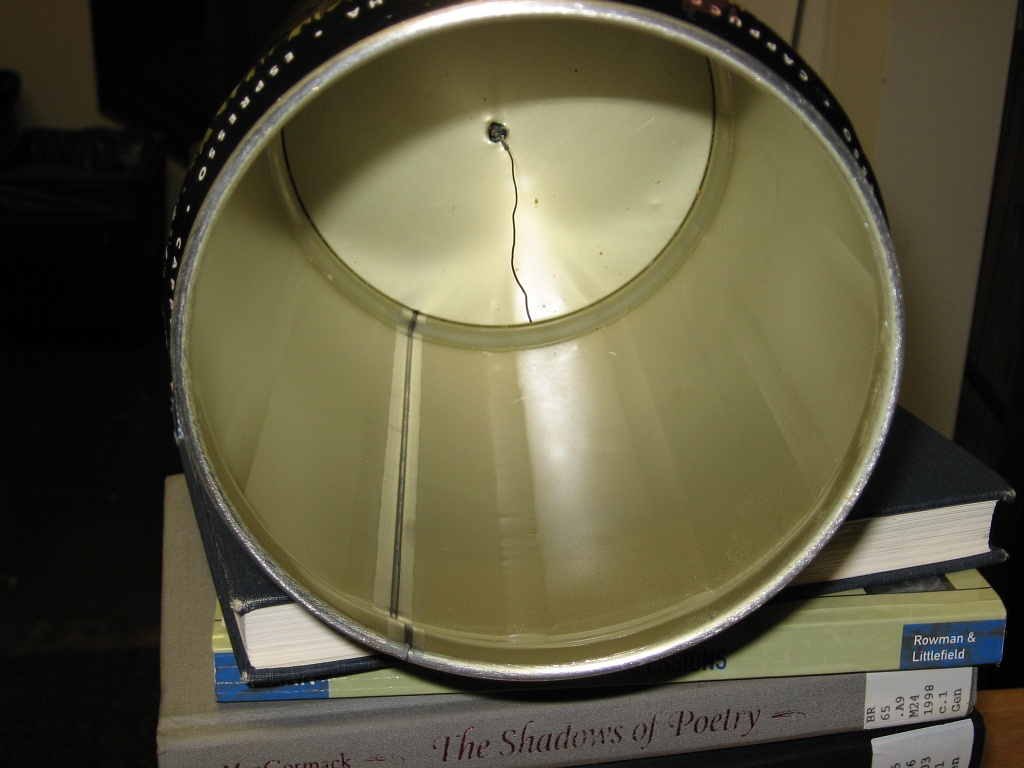
A simple ion chamber to measure radioactivity
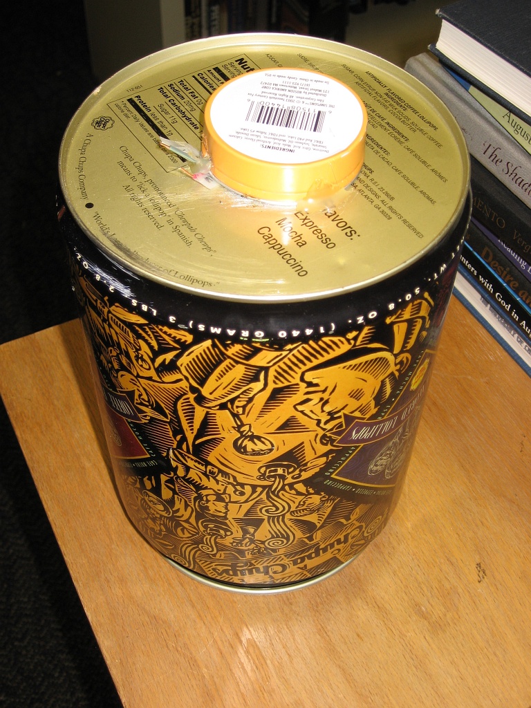
I built Charles Wenzel's simple ion chamber. It creates an electric field inside the can via a battery. A wire in the center of the can, isolated from the can, is connected to a transistor pair called a Darlington, essentially a pair of amplifiers. When ionizing radiation creates an ion in the can, the electric field drives the ion towards either the can or the wire, depending on the charge of the ion. This creates a very small current which barely turns on the darlington to allow the voltmeter to measure a small change in voltage.

I could easily up the voltage on the chamber by snapping in more 9V batteries.
You can also light things up nicely: I had 122V DC at my disposal, although I wouldn't recommend running it for very long. Based on a rough calculation, the 40W lamp would run for an hour on this battery set, but the batteries aren't meant to source this much current (about 1/3 Amp).

I had an easy way of changing the chamber voltage, 9 volts at a time, so I measured the quiescent voltage and the voltage with a smoke detector alpha particle source in the chamber. I sealed the chamber by placing it on a sheet of aluminum foil.
| Voltage | Null voltage | alpha source |
| 36V | 4.8mV | 9.1mV |
| 45V | 7.1mV | 14.9mV |
| 54V | 11.3mV | 20.6mV |
| 63V | 23.4mV | 41.5mV |
| 72V | 1230mV | 1915mV |
| 81V | 12000mV | 12000mV |
Dear Blogger, why do you mess my table so?
Friday, July 06, 2007
Geiger counter clicker schematic
By long-delayed request, a schematic of the geiger counter clicker unit I built to supplement the Aware Electronics RM-70. I'm not very good at creating electrical schematics, so please be gentle.
Schematic in TinyCAD.

Schematic as PNG.
Schematic in TinyCAD.
Schematic as PNG.
Friday, February 17, 2006
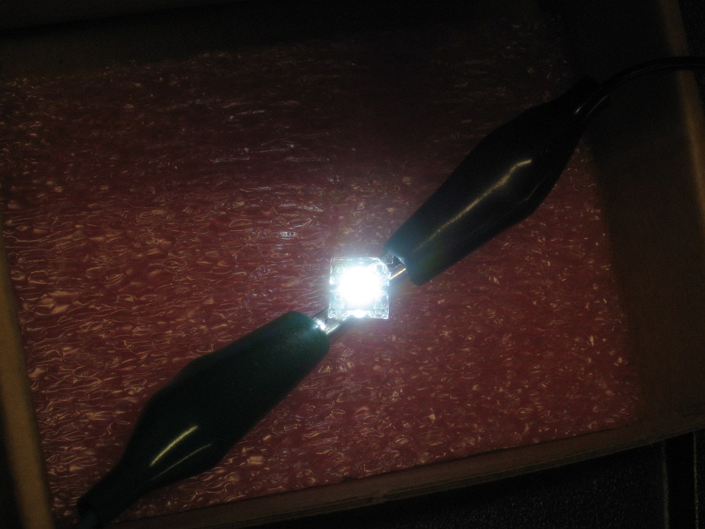
Transmitting audio over light (laser or LED)
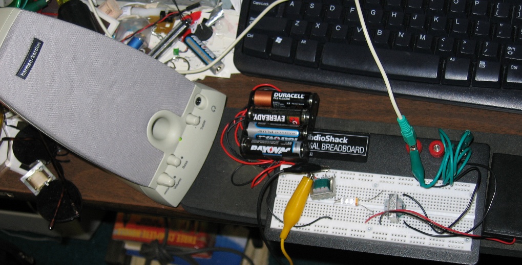
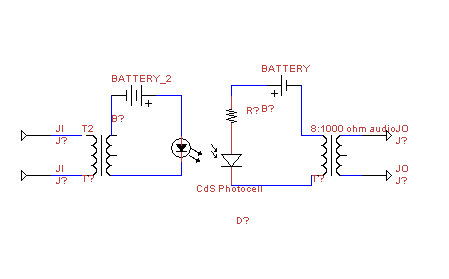
Want to send your audio information via a light wave across the room? I built this simple circuit with some modifications that transmits an audio signal via light. The signal simply amplitude modulates the light intensity (aka AM) of a LED and a receiving cadmium sulfide photocell changes its resistance as the intensity varies. Both sides have 8 to 1000 ohm audio transformers, although on my circuit I ended up using the transformer on the receiving side as a voltage booster. I also added a battery and resistor to the photocell receiving side.
Be careful--I used an LED because I destroyed a cheap laser pointer when trying the first circuit. The problem with it is the sound card audio is approximately 1 Volt AC at max, and this gets converted to ~12.5V on the other side (although I found output was usually around .5 V on the sound card and ~4 to 5V on the other side of the transformer). At least that's what I measured--I've seen people read 4V on sound cards, but I don't know which is correct.
I ended up using a white LED since it was my brightest LED, but I also have a superbright red LED that seems to work even better.


This is a 343KB video of the circuit in action. I block the beam and the sound volume dips.
I hate using the future tense on the web, so I'll say I promise to post a circuit diagram soon... --- and here it is! (keep in mind it's a CdS photocell, not a photodiode. I couldn't find the symbol in TinyCAD).
Forrest Mims wrote the book on this sort of thing, and there is a better circuit in Getting Started in Electronics, simply the best starter book for people interested in electronics and how things work.
Be careful--I used an LED because I destroyed a cheap laser pointer when trying the first circuit. The problem with it is the sound card audio is approximately 1 Volt AC at max, and this gets converted to ~12.5V on the other side (although I found output was usually around .5 V on the sound card and ~4 to 5V on the other side of the transformer). At least that's what I measured--I've seen people read 4V on sound cards, but I don't know which is correct.
I ended up using a white LED since it was my brightest LED, but I also have a superbright red LED that seems to work even better.
This is a 343KB video of the circuit in action. I block the beam and the sound volume dips.
I hate using the future tense on the web, so I'll say I promise to post a circuit diagram soon... --- and here it is! (keep in mind it's a CdS photocell, not a photodiode. I couldn't find the symbol in TinyCAD).
Forrest Mims wrote the book on this sort of thing, and there is a better circuit in Getting Started in Electronics, simply the best starter book for people interested in electronics and how things work.
Saturday, February 12, 2005
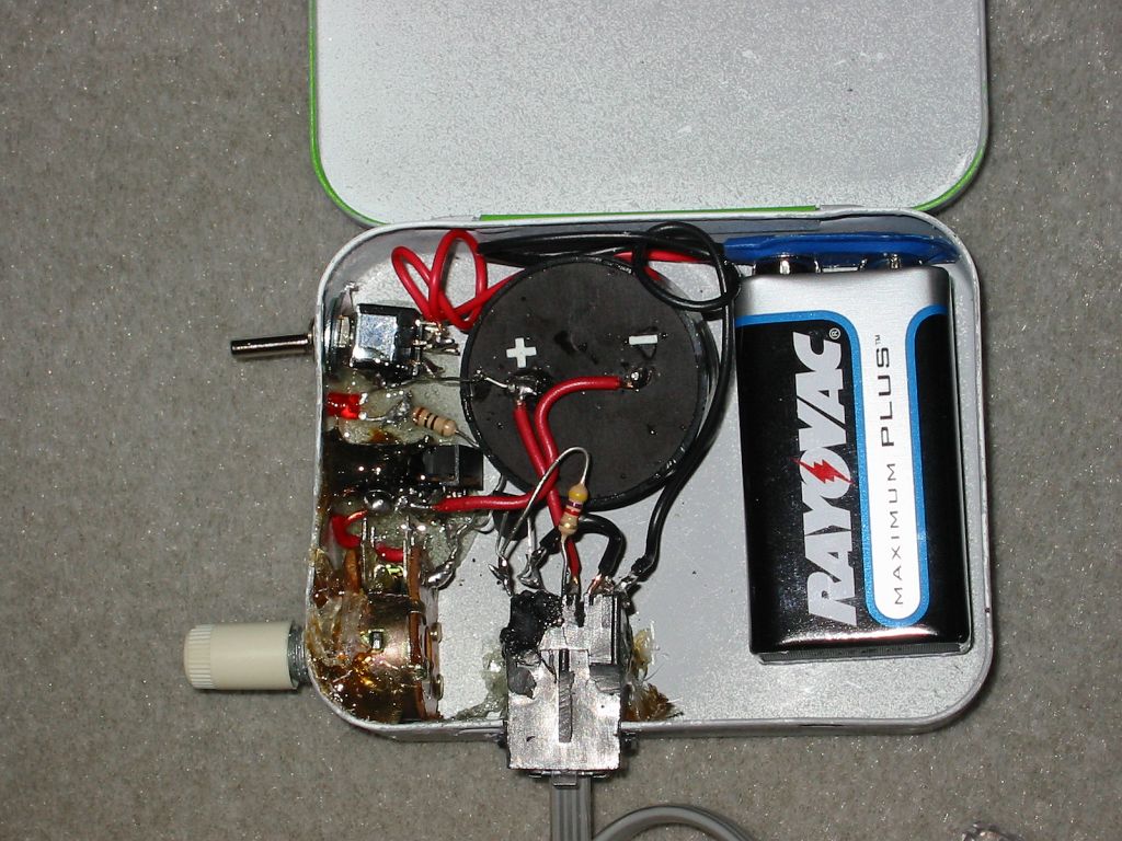
Geiger counter photos
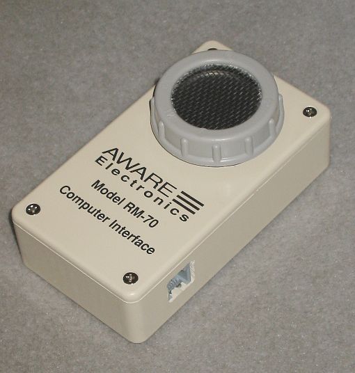
The clicker unit attached to the geiger counter
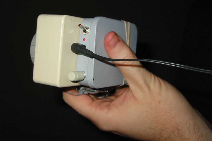
I made the clicker unit with robust design in mind. Therefore, I epoxied everything to the case and it looks really crappy, but it's not going to fall apart in someone's pocket. You can see the basic circuit--9 volt battery switched, which powers the counter through the phone jack. The detection indicator is a negative voltage swing on another line from the phone jack, which switches a PNP transistor. The transistor opens to allow current to flow through the potentiometer, the headphones, and the speaker. The LED is controlled directly by the indicator pulse, without transistor switching.
What's wrong with the design? The headphones should be bypassed when they aren't plugged in, but they aren't, so the speaker does not click without headphones. And, when the headphones are in, there isn't enough oomph to drive the 8 ohm speaker. I tried bypassing the headphones, but I didn't try until after I had assembled the unit, and everything was too cramped to solder.
P.S. What software tools do you use to generate nice schematics? Preferably free or open-source.
Subscribe to:
Posts (Atom)