
Showing posts with label radio. Show all posts
Showing posts with label radio. Show all posts
Sunday, October 23, 2022
Grabbing a NOAA weather satellite download
NOAA has a set of older LEO weather satellites that send an analog signal of the the sensor data they receive, one line at a time, and these are easily listenable with modest equipment.
I picked up this image from NOAA 18 this morning, just by chance (I had just come in from listening to the ISS repeater and happened to leave the SDR listening on 137MHz).
Recording via SDRSharp, WFM modulation, 35kHz bandwidth, gain at 30-40dB with a short vertical monopole indoors. Decoded with the appropriately named https://noaa-apt.mbernardi.com.ar/

Saturday, February 09, 2019
Image received from the International Space Station
I received an image that was being transmitted from the International Space Station as it passed nearly overhead this evening. They broadcast at about 25W of power at 145.800 MHz; an amount that is easily heard and received since the communication is line-of-sight and only a few hundred miles away. They only use it on occasion so it was nice to hear they were planning on a few days of sending images. I used a generic SDR receiver and a simple dipole and piped the audio output to MMSSTV. Some of the noise in the center of the image was because I forgot to correct the receiver for the Doppler shift of the ISS as it passed by.


Thursday, March 10, 2011
Audio stereo isolation circuit diagram
Two years I made an audio stereo isolation transformer, suitable for getting rid of ground loop problems in a line-level audio connection. Here's a simple circuit diagram that attempts to match the colors of the physical device.

http://www2.lib.uchicago.edu/~dean/blog/isolation-transformer.dsn
Circuit diagram for TinyCAD.

http://www2.lib.uchicago.edu/~dean/blog/isolation-transformer.dsn
Circuit diagram for TinyCAD.
Monday, September 20, 2010
fluorescent light runs at 25kHz
The newish fluorescent light (well, added in 1999 to make up for a lost skylight) fixture in the RAS office must have an electronic ballast that runs at 25kHz, as that is a strong signal that pops up on the oscilloscope & antenna when that light circuit is running. The older fluorescent lights are probably ancient magnetic ballasts.
...I'm sure y'all care.
...I'm sure y'all care.
Wednesday, October 28, 2009
Looking at the radio spectrum with an oscilloscope
One of the things I've always been interested in was radio; and part of that was scanning as much of the radio spectrum as possible to hear what was out there. As a kid, this was my father's shortwave receiver; I spent hours twirling the giant frequency handwheel on that radio absorbing every foreign radio broadcast I heard and wondering what the various weird noises I heard were.
For instance, at times there would be a overwhelmingly loud, rapid "thump-thump-thump" noise that was fairly broadband across a few megahertz. I asked my father about that and he called it the "Russian Woodpecker", an over-the-horizon radar system that used frequencies that were normally used by shortwave broadcasters. If I stayed up long enough at night, I would begin to pick up the European broadcasters waking up at dawn with their early morning news broadcasts.
One thing about most radios is you are only tuned to one frequency at a time. You get a limited amount of bandwidth around that frequency depending on how the radio works. It's hard hence to compare the strengths of two stations simultaneously without resorting to memory tricks or rapid tuning.
With a fancy piece of equipment called a spectrum analyzer, you can see a wide range of frequencies at once and see various radio stations, peaks, etc. To some extent you can do this with a PC sound card hooked up to the audio output of the radio, but again you are limited in bandwidth. See the laptop display below, for instance.

The generalized setup. An antenna, a diode detector, and an oscilloscope. The PC is not being used in this particular example.
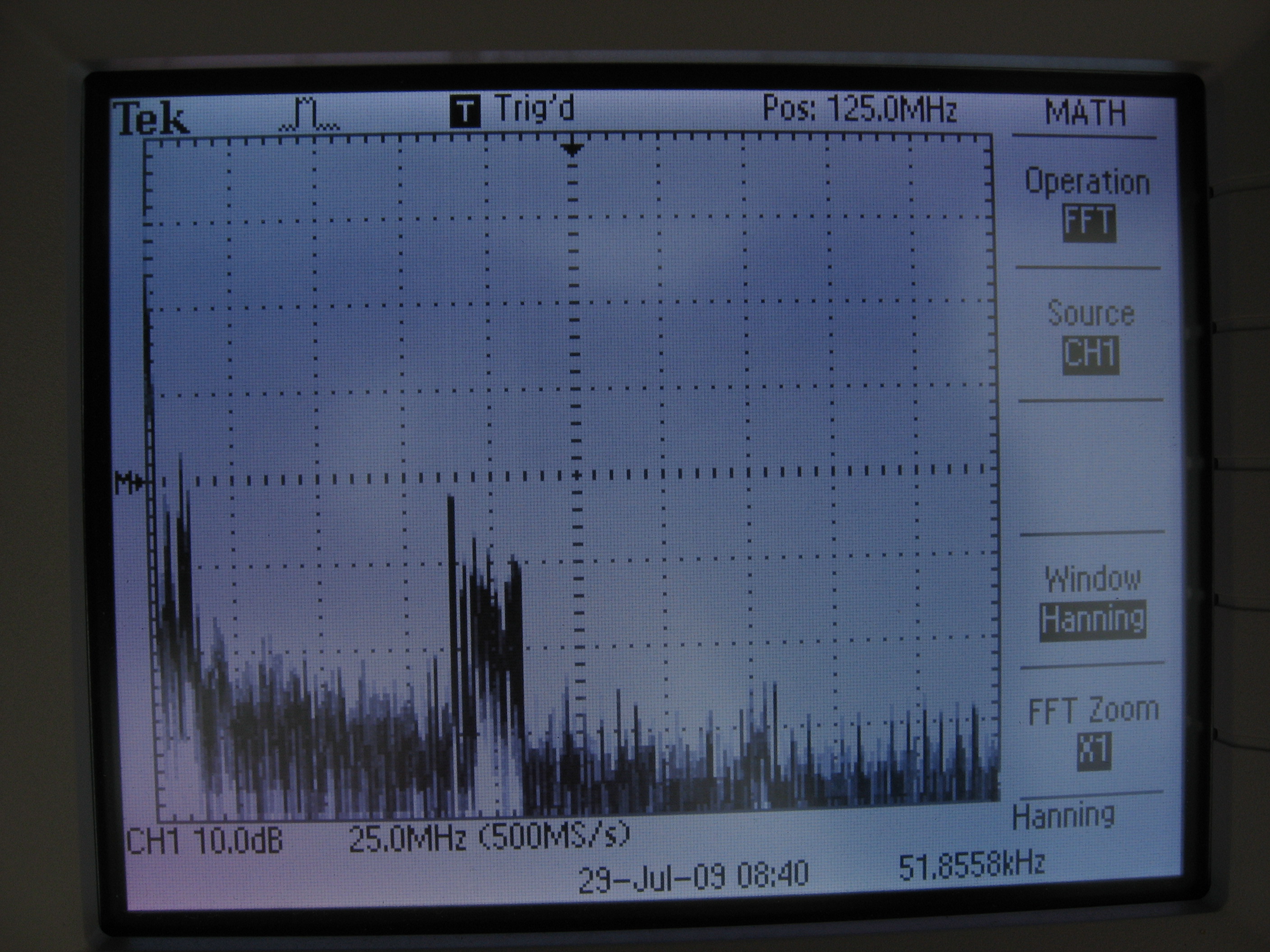
What amazes me is a sub-$1000 digital oscilloscope that is advertised as a 40MHz scope, that is, it can display signals up to 40MHz in frequency, can in a FFT mode display the signals up to 500MHz and essentially function as a spectrum analyzer.

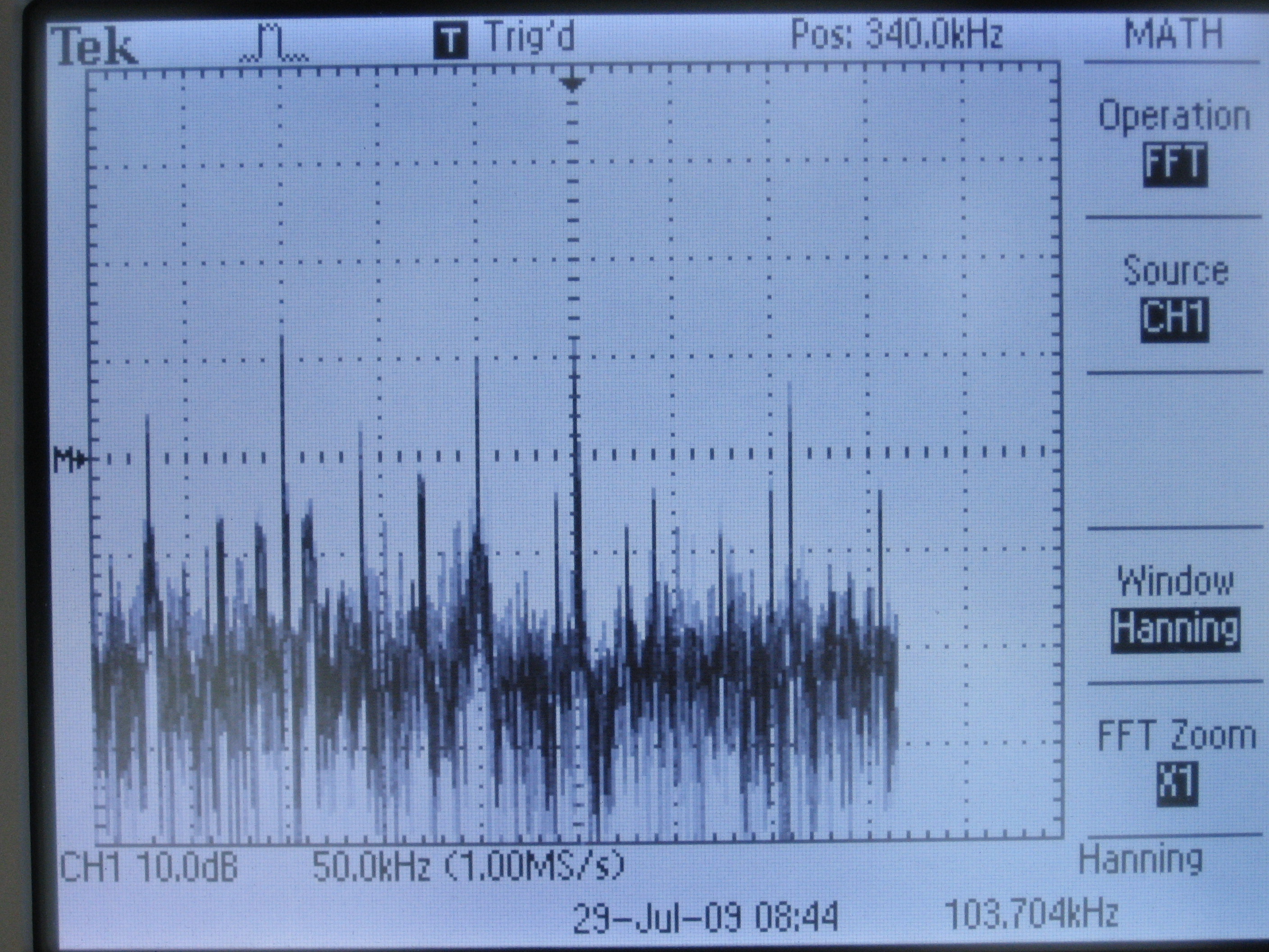
An overview of the Chicago radio spectrum
The key things to note here are intensity is the vertical, frequency is the horizontal. Near the upper right corner is "POS:", which notes the frequency at the center of the display. At the center bottom is the horizontal scale, in this case 25MHz per big division. So the bump of stuff to the left of center in this image is at about 125MHz-25MHz= 100MHz, which is in the FM Radio band.

FM Radio band.
In the FM band, you can see that there are plenty of stations filling the available channels. The isolated peak on the left is WHPK-FM, the campus radio station running at 100W, and is about two blocks from my location. It sits in the non-commercial section of the FM band.

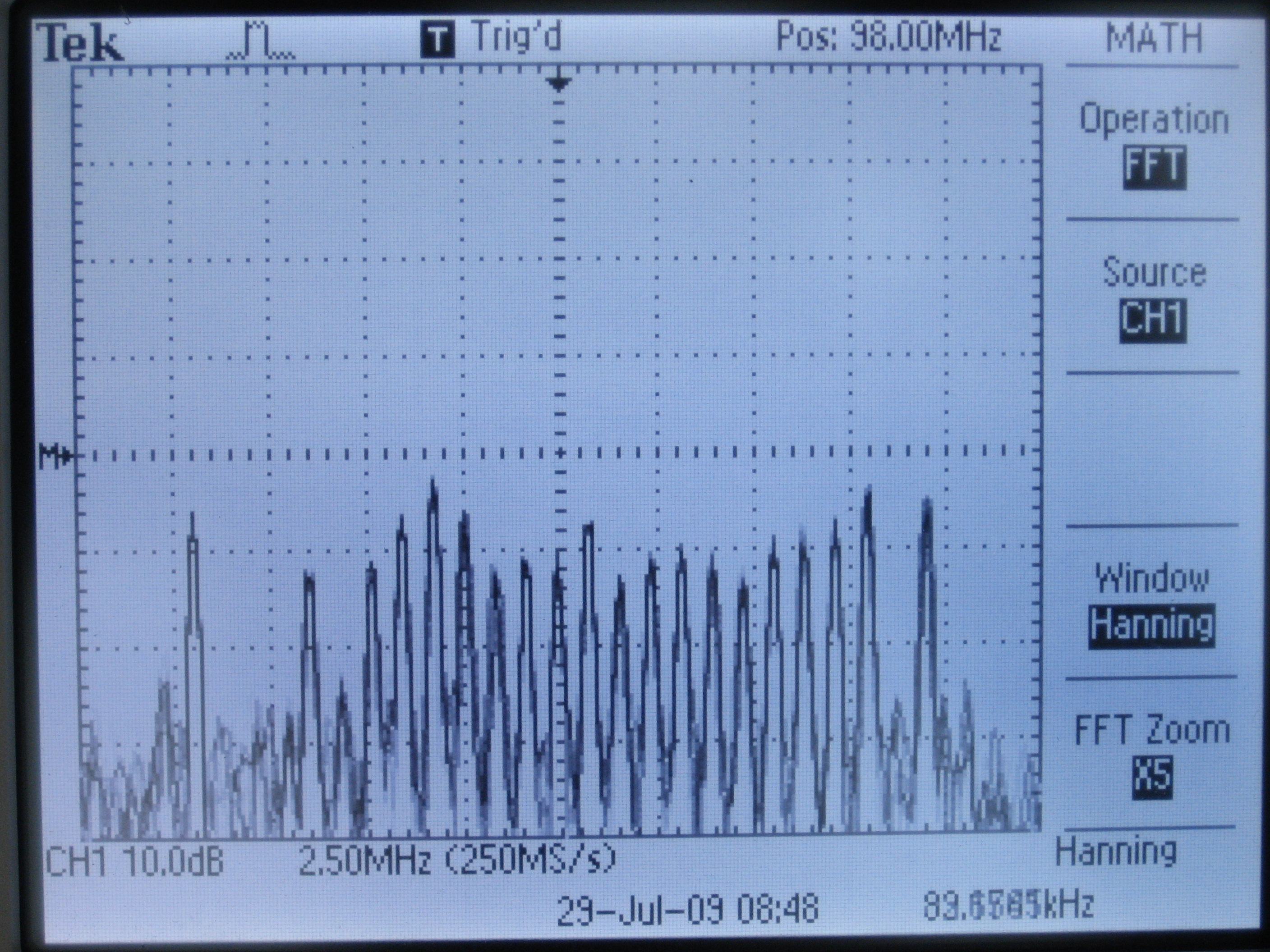
AM Radio band
The AM radio band at my location is dominated by WRTO-AM at 1200kHz. This station gets into any cable, any wire, and if you have any rectification from a piece of corrosion, or just input an antenna directly into a PC, you will get La Tremenda.

Looking closer at 1200kHz
If you look closer at WRTO's signal, you see it has a strong carrier and two sidebands further out at about 12.5kHz out. Now, when I originally saved this image, I thought I was seeing the audio sidebands of the AM signal. If the AM radio station broadcasts a single note at 440Hz, for instance, you'd see the strong carrier, and two line peaks on either side at 440Hz away. But here they are all the way out at 12.5kHz, a frequency that is present in "ssss" or a cymbal but little else. And especially not normal AM radio broadcasting, which is limited by the FCC to just a tad over 20kHz bandwidth, so the stations have to drop all their treble sounds.
It appears these outliers are the dreaded "HD radio", a hybrid technique that transmits the audio in two sidebands that exceed the normal width of an AM broadcast. Unfortunately this process violates old technical standards that allowed stations to coexist with each other. It was dropped in favor of a proprietary digital standard that allows big stations to use more bandwidth and clog up the airwaves with digital hash noise.

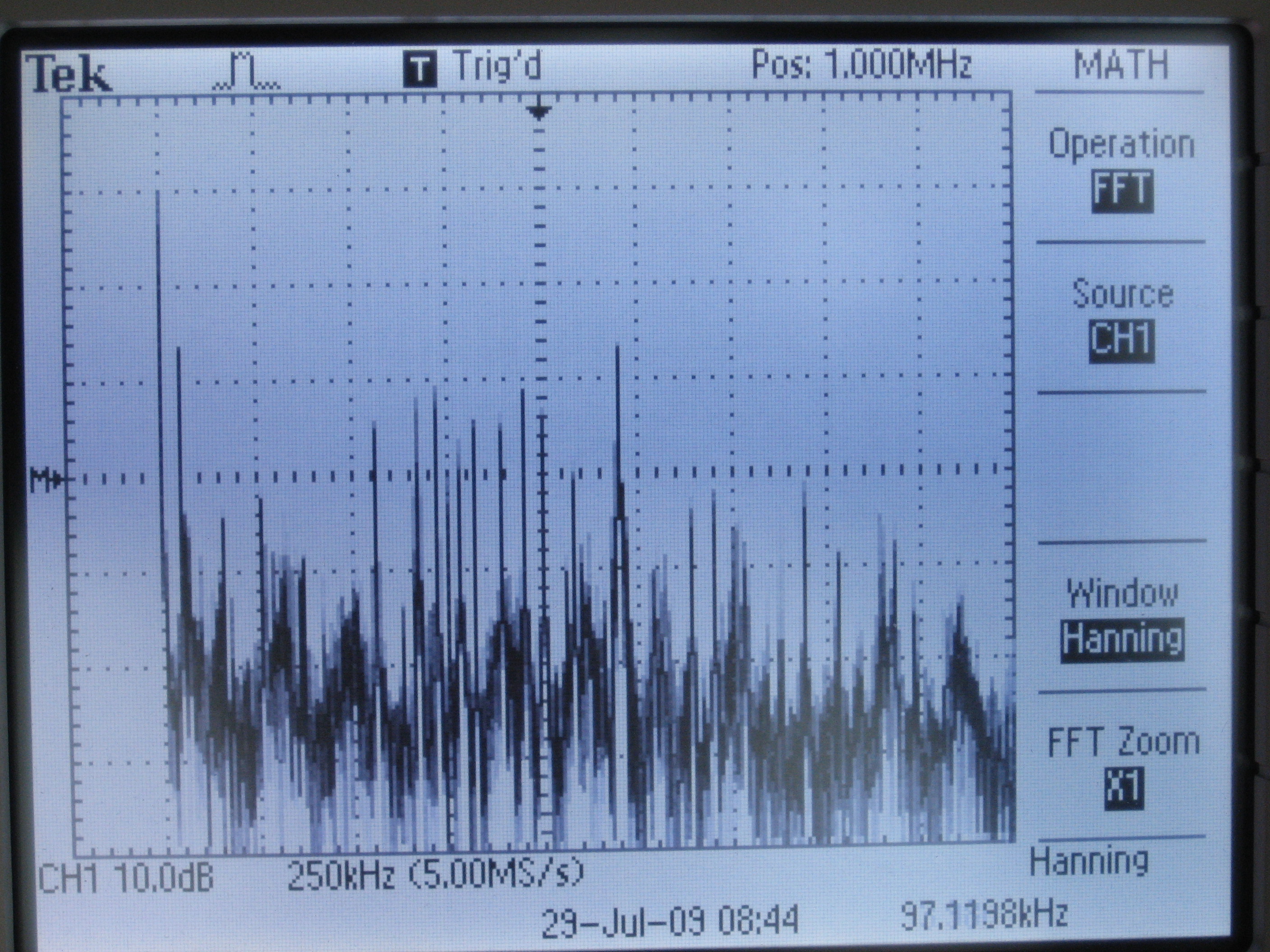
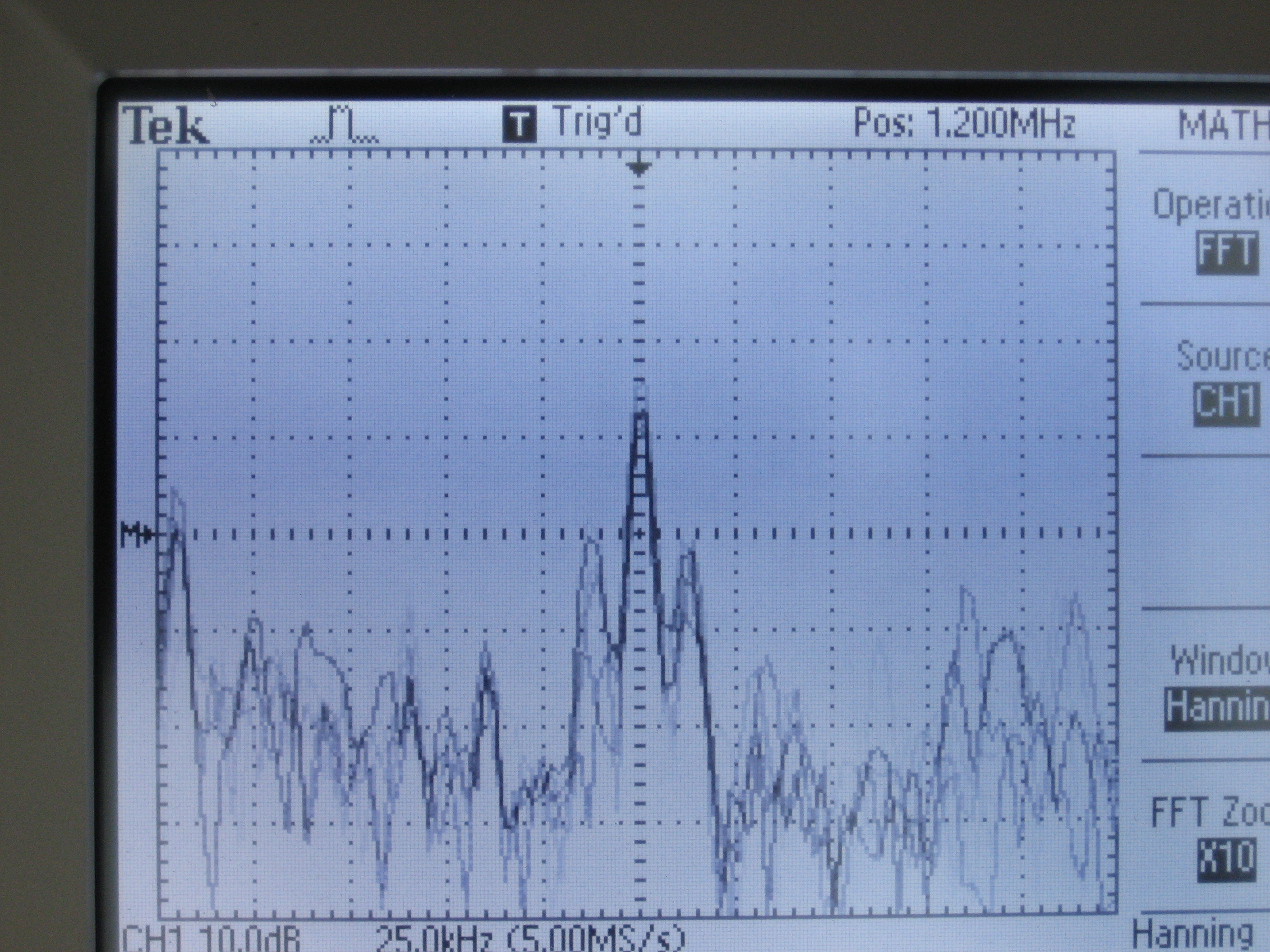
Below the AM radio band
Just below the AM band is the rest of what is known as Mediumwave or Medium Frequency, which then transitions into LW or longwave; this band is notable for non-directional beacons for aeronavigation, DGPS (or differential GPS), and lots of noise. I will have to take another spin around this band to listen to some of those peaks and see if they are real signals.

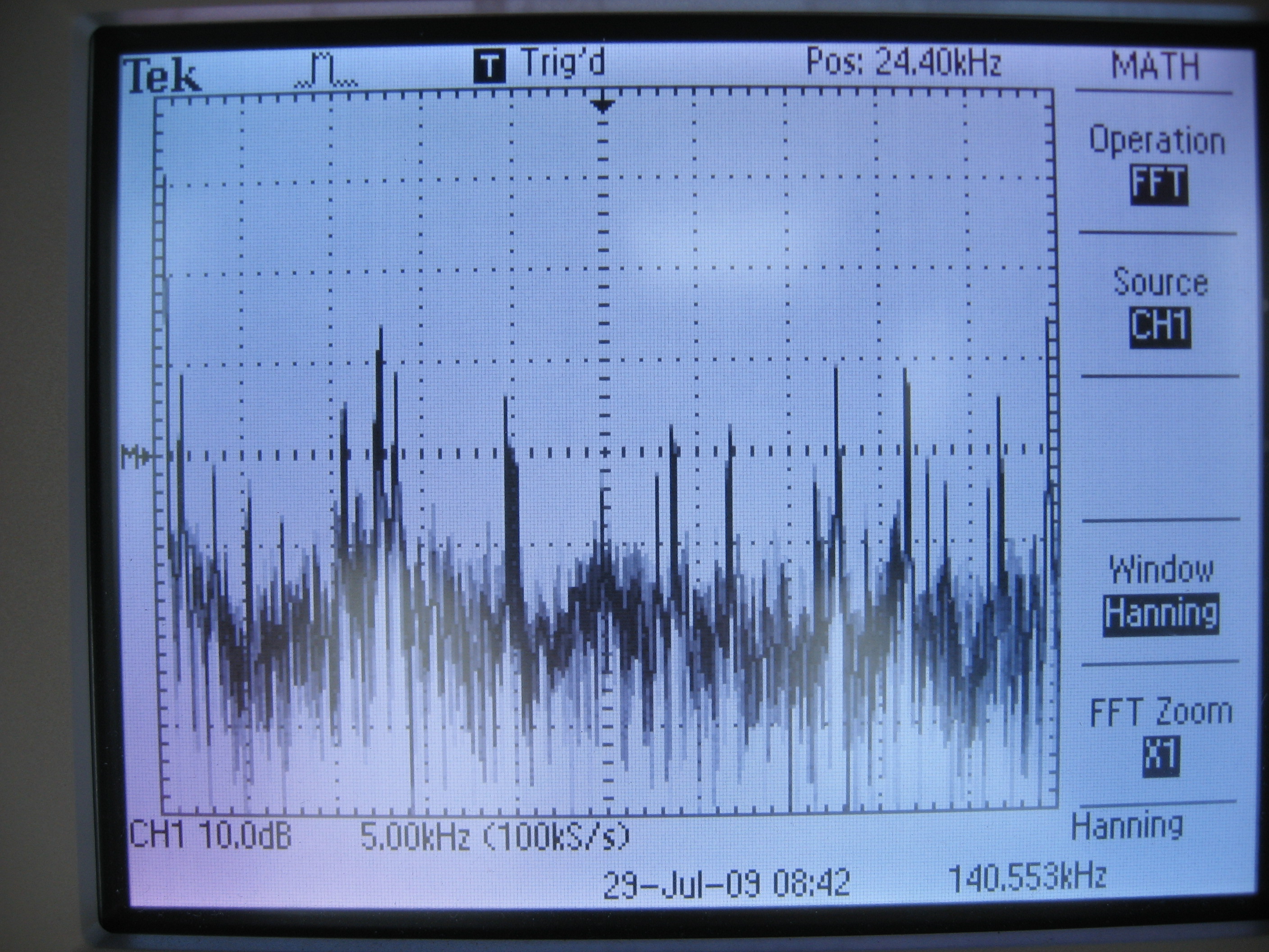
VLF Radio spectrum
Once you get down here, you start running into lots and lots of switching mode power supply noise. Various Navies around the world still broadcast on this frequency for radionavigation and uninterruptible worldwide coverage. Two of the stronger signals to the left are probably the Russian radionavigation system at 11.9kHz and 12.6kHz.
I have some other snapshots showing excellent response to the shortwave radio broadcasters of the world. It's amazing to see the whole shortwave spectrum at once instead of moving around frequencies one kilohertz at a time.
For instance, at times there would be a overwhelmingly loud, rapid "thump-thump-thump" noise that was fairly broadband across a few megahertz. I asked my father about that and he called it the "Russian Woodpecker", an over-the-horizon radar system that used frequencies that were normally used by shortwave broadcasters. If I stayed up long enough at night, I would begin to pick up the European broadcasters waking up at dawn with their early morning news broadcasts.
One thing about most radios is you are only tuned to one frequency at a time. You get a limited amount of bandwidth around that frequency depending on how the radio works. It's hard hence to compare the strengths of two stations simultaneously without resorting to memory tricks or rapid tuning.
With a fancy piece of equipment called a spectrum analyzer, you can see a wide range of frequencies at once and see various radio stations, peaks, etc. To some extent you can do this with a PC sound card hooked up to the audio output of the radio, but again you are limited in bandwidth. See the laptop display below, for instance.

The generalized setup. An antenna, a diode detector, and an oscilloscope. The PC is not being used in this particular example.
What amazes me is a sub-$1000 digital oscilloscope that is advertised as a 40MHz scope, that is, it can display signals up to 40MHz in frequency, can in a FFT mode display the signals up to 500MHz and essentially function as a spectrum analyzer.
An overview of the Chicago radio spectrum
The key things to note here are intensity is the vertical, frequency is the horizontal. Near the upper right corner is "POS:", which notes the frequency at the center of the display. At the center bottom is the horizontal scale, in this case 25MHz per big division. So the bump of stuff to the left of center in this image is at about 125MHz-25MHz= 100MHz, which is in the FM Radio band.
FM Radio band.
In the FM band, you can see that there are plenty of stations filling the available channels. The isolated peak on the left is WHPK-FM, the campus radio station running at 100W, and is about two blocks from my location. It sits in the non-commercial section of the FM band.
AM Radio band
The AM radio band at my location is dominated by WRTO-AM at 1200kHz. This station gets into any cable, any wire, and if you have any rectification from a piece of corrosion, or just input an antenna directly into a PC, you will get La Tremenda.
Looking closer at 1200kHz
If you look closer at WRTO's signal, you see it has a strong carrier and two sidebands further out at about 12.5kHz out. Now, when I originally saved this image, I thought I was seeing the audio sidebands of the AM signal. If the AM radio station broadcasts a single note at 440Hz, for instance, you'd see the strong carrier, and two line peaks on either side at 440Hz away. But here they are all the way out at 12.5kHz, a frequency that is present in "ssss" or a cymbal but little else. And especially not normal AM radio broadcasting, which is limited by the FCC to just a tad over 20kHz bandwidth, so the stations have to drop all their treble sounds.
It appears these outliers are the dreaded "HD radio", a hybrid technique that transmits the audio in two sidebands that exceed the normal width of an AM broadcast. Unfortunately this process violates old technical standards that allowed stations to coexist with each other. It was dropped in favor of a proprietary digital standard that allows big stations to use more bandwidth and clog up the airwaves with digital hash noise.
Below the AM radio band
Just below the AM band is the rest of what is known as Mediumwave or Medium Frequency, which then transitions into LW or longwave; this band is notable for non-directional beacons for aeronavigation, DGPS (or differential GPS), and lots of noise. I will have to take another spin around this band to listen to some of those peaks and see if they are real signals.
VLF Radio spectrum
Once you get down here, you start running into lots and lots of switching mode power supply noise. Various Navies around the world still broadcast on this frequency for radionavigation and uninterruptible worldwide coverage. Two of the stronger signals to the left are probably the Russian radionavigation system at 11.9kHz and 12.6kHz.
I have some other snapshots showing excellent response to the shortwave radio broadcasters of the world. It's amazing to see the whole shortwave spectrum at once instead of moving around frequencies one kilohertz at a time.
Monday, June 08, 2009
Audio isolation transformer
I used to record audio off my Tivo on my desktop computer--but when I had the cable TV connected, I would get a loud hum. The reason for this is related to the idea of "ground" in electrical systems, which are used as a reference point for zero voltage and/or safety purposes. The kicker was the cable TV cable offered a different path to ground compared to the PC's ground.
For consumer generic audio connections, the audio signal (a varying AC voltage of about one volt) is compared to the ground of the system. Hence the two connectors on an RCA connector, signal and ground, or three connectors on a stereo jack: left, right, and ground. If your ground happens to be varying up and down at 60 times a second (because it's not a good ground, for instance), you will also get that hum on your output.
For some professional audio systems, the reference ground is brought with the signal, so you have three connections for any channel. When both the signal and ground vary up and down in sync, it's easy to subtract the pickup noise and have a clean signal.
In simple, single systems, either approach works fine. The problem is when you start interconnecting equipment.
I made a stereo isolation audio transformer to solve this problem. The left and right channels enter a 1:1 600ohm audio transformer, which transmits the audio signal (which is AC) but blocks any DC connection. This prevents ground loops and currents between the two devices. I got the two transformers from old modems. One of the jacks is a fancy panel mount, the other is from an old sound card, and this old one is actually needed, because it is plastic, isolating it from the case, which is connected to the ground of the panel mount jack. Of course, I put everything in an Altoids tin.
I suppose it would also help if I put some ferrite on the inputs to also reduce RFI/EMI problems, but I haven't yet. Just having this device between a shortwave radio and a PC has reduced interference pickup quite a bit.
You can see more photos of the build at http://www.flickr.com/photos/dwarmstr/sets/72157604679420753/. Essentially, 1. Measure and Mark your holes. 2. Make a small punch to keep drill centered. 3. Drill a pilot hole, then the right size. 4. Solder the connections. I used a multimeter to figure out which connection was which on the transformers. 5. Hot glue for stability.
Parts cost: about $2.50 for the 3.5mm stereo panel mount. Everything else I scrounged for from old parts, not counting my time. Here's the equivalent commercial product at $32: http://www.amazon.com/3-5mm-Stereo-Audio-Isolation-Transformer/dp/B001GUS7EO. I do enjoy the look of that commercial case.
Tuesday, April 21, 2009
Spy numbers station on shortwave
I've heard this strong station several times now over the past year, usually later at night. It always broadcasts at 5900 kHz (or now that I think about it, have I picked it up at 9800kHz?). I picked this up Monday night/Tuesday morning, April 21st, just after 00:34 CDT (5:34 UT).
The station is pretty strong here in Chicago, with only occasional fading, and it sends a modified CW signal that can be picked up with any shortwave receiver. It only uses three digit code letters in groups of five: those Morse Code letters that are described by three combinations of dots and dashes, minus S and O, which are dot-dot-dot and dash-dash-dash.
5900-spystation.mp3 audio file, 7.43MB
Decoded, the file yields this:
DAUWN WIWNW GDNWR UTWAT RGAID INWTA NUGIW UIWWA GINRT NRDWI DNRUT RDAUG NNAII TWIIR UDDNA ATDGT NUART DTIWU IUWWI TINUW ADNIT RRRWT DATRA DUWGW NGINI UTDTR IDIRA DRUDD NIDTU IIDRG URWUU GTTNI UIWIR UITND ATTDI WARGR DGTGD DWIRD AIIAI ARDTI TIGDU GRUWI AUTRT NTWNU GRUUU TUGUG AAARI TRRNG TTDAA WUWGU NNATW WNGRN TNRAN DRUTN DWUGU RDAUN RGGNN TNWNN WDGDD WARGA DDGNN DUDTA RRNNN RWTNU RUWTI GRTIA UDAAN ITIUG UIIAR WIUTU IATNT UDNGN ARGNT TAAWU WUADN DAARW INRGR GNNAG ADGRU GNWWR GWGUD WDNNA URRAR WITIN RRDAD AIDRR GUAUG INANU DIWUI WAGAN NRUUN AWRAD DWRNR UTRAU INIDR UITUN ATDUG RUUAA UIGWT DAIUI AIRRD ANAIN IDATI WDIUG WTNAD UNRAI GNDTR ADNNI DUNGR RDWDI UGTUD TDATG GIGUG IAANA DRDTD TGIGN GWUNN GWIII ADWDD
The actual contents of this message are presumbly only known by the intended spy and the agency that sent the one-time pad message to them.
Tuesday, April 07, 2009
Radio astronomy dish raising

Joe Cottral managed to get a spare 2.5m satellite dish from western Illinois to Chicago. The rest of the RAS had the responsibility of getting the dish from ground level up to our 6th floor aerie. We decided on raising the dish as reasonably quickly as possible, to reduce the annoyance factor for all non-involved. We also picked after much observation and discussion to raise the dish via the southeast corner of Ryerson which is an elevated turret. The reason being the turret allowed easy transfer over the parapets of Ryerson. The loading dock offered easy vertical lift, and the fire escape offered quick one-story lifts, but in the end, Lui's suggestion of the turret was the superior option.
Now, we have to 1. acquire a receiver capable of 1420MHz and 1.6GHz-ish, 2. Clean up the dish mounting steel, 3. Mount the dish on Ryerson with lots of Quikcrete, 4. Get microwave-capable cable, 5. get a low-noise-amplifier, and 6. put it all together. Minor bit there. Oh yes, and decide where to place it on the roof.
Sunday, February 01, 2009
The radio electromagnetic spectrum
This is a great chart of the entire electromagnetic spectrum. If you interested in the more organized allocations of the radio region, see this very detailed PDF chart.
Sunday, January 25, 2009
Microwave meter videos
I made a few videos of the simple microwave / 2.4GHz meter dealing with work office's microwave oven--woe be unto whomever hangs around the hinge.
The first is a full examination of the space of the microwave oven, and is entirely inappropriate for those with short attention spans (stick to the second video, you).
This one is a short proof the detection is when the microwave oven is busily heating my hot water for tea.
The other amazing news is there is a very strong microwave signal that the northwest corner of the roof of Ryerson intercepts that appears to be coming from either the Admin building or the hospital: it strongly peaks in the southwest direction, almost pegs the meter on the 200mV scale, and when I added a headphone to the meter I could audibly hear some sort of signal that reminded me of a TV video sync noise.
What is this signal? Am I hearing a horizontal sync? Or is there some other signal that has a repetitive sync noise that runs at 12-18 kilohertz?
Thursday, January 22, 2009
Chicago FM radio band scan
Here's a band scan of all FM radio stations heard Wednesday night in Chicago with a Degen 1103. I attached it to two random length wire dipoles, oriented north/south and east/west and could switch between the two.
I used V-Soft's signal strength database to ID the strongest stations. This helps when not all stations are in Chicago.
For medium and low strength stations, I used the FCC database for various queries:
for all stations within 100km of me, for instance, click here.
You can get radio coverage maps from the FCC, or more refined maps from Radio Locator that show how likely it is to pick up the station.
Antenna is the orientation of the dipole; so the note "east/west" means the wire is strung east/west and sensitive to signals coming from the north or south.
Station IDs were either heard, inferred from strength, music type, from the list of Chicago stations, or best guess from distant station lists.
Since formatting is horrible, here is the Excel spreadsheet.
If a frequency is not listed, it was a channel subject to bad interference from a neighboring station.
The idea of finding the clear channels is to find one suitable for meteor scatter work: a normally too-distant station (because it is over the horizon) can suddenly boom in because the signal is reflected from a ionized meteor trail halfway between the listener and broadcaster.
Some interesting results: WXXC and WBYR, located in Marion and Fort Wayne, IN, at 150 miles away.
I used V-Soft's signal strength database to ID the strongest stations. This helps when not all stations are in Chicago.
For medium and low strength stations, I used the FCC database for various queries:
for all stations within 100km of me, for instance, click here.
You can get radio coverage maps from the FCC, or more refined maps from Radio Locator that show how likely it is to pick up the station.
Antenna is the orientation of the dipole; so the note "east/west" means the wire is strung east/west and sensitive to signals coming from the north or south.
Station IDs were either heard, inferred from strength, music type, from the list of Chicago stations, or best guess from distant station lists.
Frequency Call sign Strength Antenna notes
87.7 WLFM-LP   spanish news (tv carrier)
88.1 WCRX  east/west dance mono
88.1 WSSD  north/south R&B / announcer talking over song
88.5 WHPK-FM strong  "very local, college"
88.9 WIIT weak east/west college
89.3 WKKC   smooth music
89.5    hip-hop
89.7 WONU   Christian
90.1 WMBI-FM strong  Christian
90.5 WRTW?   rap
90.7 WAUS weak  classical
90.9 WDCB  north/south
91.1 WGSI weak  focus on the family / fox news / faint music
91.5 WBEZ strong
91.9 WJCH   piano music
92.3 WPWX   rap
92.5  clear (trace)
92.7 WCPT
93.1 WXRT-FM
93.3  clear (trace) north/south
93.5 WVIX   spanish
93.9 WLIT-FM   talk
93.7 WTRX-FM or WBCT  north/south country
94.1  clear (trace)
94.3 WJKL   christian
94.7 WLS-FM   rock
94.9  clear (trace)
95.1 WIIL
95.5 WNUA   jazz
95.7  clear (trace)
95.9 WEFM or WERV-FM  east/west jazz
96.3 WBBM-FM   rock?
96.5  clear
96.7 WSSR
97.1 WDRV
97.3 WQBW? faint  "Milwaukee, WI 104mi"
97.5 WHMS   lite
97.9 WLUP-FM   MISSING?
98.1 WIBN or WZOE  north/south "seeger, classic hits radio online"
98.3  strong  local CPU
98.7 WFMT   classical
98.9 WBYR   "fort wayne, IN ""The Bear"" 153mi range"
99.1 WXTT  east/west "Extra rock Danville, IL 114mi"
99.5 WUSN   country
99.9 WCPQ strong
100.3 WILV   70's
100.5  clear (trace)
100.7 W264BF  east/west Christian
101.1 WKQX   alt
101.3  clear
101.5 WBCH? WBNQ? WNSN?   modern WBCH? WBNQ? WNSN?
101.9 WTMX   R&B
102.1  clear (trace)
102.3 WYCA  east/west gospel
102.7 WVAZ   love or Christian
102.9  clear (trace)
103.1 WVIV-FM   spanish
103.5 WKSC-FM   modern/dance
103.7  clear (trace)
103.9 WXRD  east/west rock (political)
104.3 WJMK   rock
104.5  clear (trace)
104.7 WCFL  east/west christian
105.1 WOJO   spanish
105.5 WJLE   country
105.9 WCFS-FM   country
106.3 WSRB   hip-hop
106.7 WPPN   spanish
106.9 WXXC   Marion, Indiana!
107.1 WZVN   rock
107.5 WGCI-FM   hip-hop
107.9 WLEY-FM   spanish
Since formatting is horrible, here is the Excel spreadsheet.
If a frequency is not listed, it was a channel subject to bad interference from a neighboring station.
The idea of finding the clear channels is to find one suitable for meteor scatter work: a normally too-distant station (because it is over the horizon) can suddenly boom in because the signal is reflected from a ionized meteor trail halfway between the listener and broadcaster.
Some interesting results: WXXC and WBYR, located in Marion and Fort Wayne, IN, at 150 miles away.
Wednesday, December 31, 2008
WWV 2009 leap second
WWV, the time station from NIST, located in Fort Collins, CO entering the New Year. With added silent leap second and odd tone for the 00 second.
WWV 2009 New Year900kB MP3. Recorded with a Degen 1103 and straight audio recording (no cable).
WWV 2009 New Year900kB MP3. Recorded with a Degen 1103 and straight audio recording (no cable).
Wednesday, December 17, 2008
a very simple 2.4GHz meter

I built a very simple meter that reads the strength of radio energy in its vicinity, without amplification or anything fancy. It picks up radio waves roughly around 1 to 3 gigahertz. It does very well in detecting cell phones, microwave ovens, and wireless access points.
On a simple level, the antenna converts radio waves into an electrical AC voltage, which is then converted by the germanium diode into a pulsing DC voltage. A capacitor stores the pulses and smooths out the pulsing and leaves a very small DC voltage, which is measured directly at a tiny multimeter I picked up at American Science and Surplus. I set the meter to DC voltage, 200mV scale.
The biquad antenna is sensitive to vertically polarized waves and slightly directional as well. A lot of designs also stick a ground plane behind it to increase the directionality, but I was looking for more of a field strength probe, rather than having an antenna that got me the most gain. It's a trade-off since the detector is so simple and without amplification, but that's what you get.

What can we measure with this meter? My standard test suite for gigahertz-ish radio frequencies is delinquent*, so all I can think of is cell phones, microwave ovens, and wireless networking. I found that the office microwave oven puts much more energy out at the hinge side of the door and a fan vent on the side than it does the meshed window. It can saturate the meter at the 200mV scale (when right next to the fan vent). Cell phones periodically check in with their towers (you can also tell this with a set of computer speakers anywhere near a GSM phone). They also do put out a bit of gigahertz radiation; I can detect them sending text messages from about six feet away and more when talking--they can also reach 200mV. Wireless 802.11b and g networks are actually pretty low-power in the scheme of things--they hard to see except close-up until they are transmitting data; then I can detect them six or so feet away. During idle they emit a "beacon" 10 times a second. The wifi antennas are also a good source for checking the polarization of the biquad--I get nearly nothing from them if I rotate the receiving antenna 90 degrees.

Outside the signal level varies greatly. There is a pervasive field which is presumably cellular networks and the addition of all the 802.11b/g/n networks. On the University of Chicago campus near the Regenstein Library the average strength varies from 0.2mV to 0.6mV, with a couple of spikes to 1.0mV. There are also areas of much stronger than ambient. For instance, outside of the Medici on 57th street the average field strength is 2-3mV and peaks at moments at 8mV. There are cellular tower antennas on a school across the street; so it seems likely the area is getting a particular sector of the tower.
I used this Field Strength Meter for 2.4 Ghz Wireless LAN as the excellent template for the project. For my version I used a standard 1N34A germanium diode--this is a more sensitive diode, and turns on at 0.3V instead of 0.6V like a standard silicon diode. I painted the diode black, as the diode proved to be photo-sensitive (all PN junctions are light-sensitive, and ones in transparent glass tubes even more so). Also, I didn't tune the capacitance at all. I then ran two wires to the inside plugs and drilled a hole in the case and hot-glued the antenna to the front of the meter. It's nice and compact, although the GP23A 12V battery in it doesn't last very long.
I could see easy modifications of this system, putting a simple FET amplifier or such to increase the meter response. If I use one of the inexpensive multimeters from Harbor Freight I might have enough room for a prebuilt circuit and a more directional antenna. I'd also like to see if I can pick up both aviation and weather radars with such a simple system. Maybe I should make a Sardine Can antenna?
*delinquent is also a synonym for nonexistent.
Saturday, June 14, 2008
Aurora activity

Despite still being in the dregs of the solar cycle the aurora occasionally really activates, and it's doing so right now. While it's daytime here in North America, the aurora is detectable by the way it distorts radio signals, producing a warbling effect on ionospherically bounced waves. The enhanced ionization also provides the ability to bounce much higher frequency radio signals than is usual, although everything is still subject to that pesky warbling.
Current observed aurora here via a NOAA satellite--it takes some time to refresh in orbit.
Spaceweather.com will have updates at some point soon; they are usually on the ball with sightings of neat events.
See the aurora forecast at UAF; which is useful, although long-term forecasts are always tough.
This alert was brought to my attention by the DXrobot, which monitors radio amateur's contacts for notes about unusual VHF radio conditions. Click here for the arcane info.
P.S. It would seem unlikely for this to be an "event" for Chicago city folk--the moon is out, light pollution is as bad as ever, clouds are coming in, and sometimes these events are short-lived.
Saturday, January 19, 2008
KXTA: the old Area 51
KXTA is a TV station in Dallas, was formerly AM radio stations in Los Angeles and Centerville, UT, and is now the airport code for the nonexistent Area 51 aka Dreamland aka the Ranch aka Groom Lake.
Wednesday, January 02, 2008
End of the year non-review #3: Civil rights and the government,
I continue running through my overflowing Google Reader "Starred Items" list.
TSA to punish fliers for facecrime a la New screening technology might detect terrorists before they act
The TSA and DIY culture clash I used to naively think as long as it passed the swab test, the TSA would professionally act accordingly and let it through, as it couldn't possibly be explosive. It seems that any exercise of your rights means immediate retaliation. The days of me refusing to let screeners and the Secret Service take photos through my cameras is probably over.
Watching FISA fizzle
Chris Dodd's actions on the telecom immunity provisions made me reconsider who I'm voting for in the primaries. More here.
DEA War on Plants
98% of all "seized marijuana plants" is wild hemp with no active drug content.
Another Man Arrested For Using Free Cafe WiFi
Ethicist Says Nothing Wrong With Using Free WiFi
When your operating system automatically connects and uses an open wifi system, how the hell can anyone claim that's illegal? Close your systems if you don't want people to use them off-site. This nonsense is why we don't currently have a ubiquitous and free wifi in dense cities.
Papers Please: Arrested at Circuit City for refusing to show ID, receipt
Remember that you are never required to show a receipt to leave a store. I never do, and it saves me much time on leaving busy stores like Fry's.
A members-only store may issue such rules, but common law says when you bought the item, it's yours. Some of the people exercising this right are jerks, but that doesn't excuse the stores and their aggressive rent-a-cops.
Insect Spy
Paranoia from activists or real? I'd really like to know--this is tantalizingly straddling the border between the kooks and real technologies. I don't trust either sides' judgement or statements on this.
California Police Camera Surveillance Increasing
The only solution now that public surveillance is out of the bag is to require the government to open up all the video and use of the system to the public. ,
Video of Man Tasered to Death
Incredibly uncomfortable, so much so I haven't watched it. Tasering is torture and our society uses them way too much. Overescalation is epidemic.
Your color laser printer has been compromised and is leaking data.
TSA to punish fliers for facecrime a la New screening technology might detect terrorists before they act
The TSA and DIY culture clash I used to naively think as long as it passed the swab test, the TSA would professionally act accordingly and let it through, as it couldn't possibly be explosive. It seems that any exercise of your rights means immediate retaliation. The days of me refusing to let screeners and the Secret Service take photos through my cameras is probably over.
Watching FISA fizzle
Chris Dodd's actions on the telecom immunity provisions made me reconsider who I'm voting for in the primaries. More here.
DEA War on Plants
98% of all "seized marijuana plants" is wild hemp with no active drug content.
Another Man Arrested For Using Free Cafe WiFi
Ethicist Says Nothing Wrong With Using Free WiFi
When your operating system automatically connects and uses an open wifi system, how the hell can anyone claim that's illegal? Close your systems if you don't want people to use them off-site. This nonsense is why we don't currently have a ubiquitous and free wifi in dense cities.
My own philosophy comes from the old days of radio, where any radio wave entering your home or your personal space was fair game to receive and listen to. Telecom interests lobbied and paid campaigns well to get the Electronic Communications Privacy Act of 1986, which suddenly made certain wavelengths illegal to listen to, all because their cordless and cellular phones were poorly designed and completely open to listening.
Australian DRM from 1923 - dumb radio idea that refuses to die
The Schneier section.
Bruce Schneier usually gets it right about security and insecurity in the world.
- We're All a Little Nervous in a post-1748 World The stupidity and inanity of prohibiting public photography and "note-taking".
- Buildings You Can't Photograph
This should be entitled "Buildings They Claim You Can't Photograph". Know your rights: The Photographer’s Right - Essay on Fear
- I have nothing to hide, why should I care if the government looks at it?
Why this argument is fallacious. - Security Theater Imagine the cost of all the security, all the waiting in security queues, all the overreactions. What does that cost us economically?
- U.S. Government Threatens Retaliation Against States who Reject REAL ID
- Interview with National Intelligence Director Mike McConnell
- The War on the Unexpected
Papers Please: Arrested at Circuit City for refusing to show ID, receipt
Remember that you are never required to show a receipt to leave a store. I never do, and it saves me much time on leaving busy stores like Fry's.
A members-only store may issue such rules, but common law says when you bought the item, it's yours. Some of the people exercising this right are jerks, but that doesn't excuse the stores and their aggressive rent-a-cops.
Insect Spy
Protesters might even nab one with a net -- one of many reasons why Ehrhard, the former Air Force colonel, and other experts said they doubted that the hovering bugs spotted in Washington were spies.
So what was seen by Crane, Alarcon and a handful of others at the D.C. march -- and as far back as 2004, during the Republican National Convention in New York, when one observant but perhaps paranoid peace-march participant described on the Web "a jet-black dragonfly hovering about 10 feet off the ground, precisely in the middle of 7th avenue . . . watching us"?
They probably saw dragonflies, said Jerry Louton, an entomologist at the National Museum of Natural History. Washington is home to some large, spectacularly adorned dragonflies that "can knock your socks off," he said.
At the same time, he added, some details do not make sense. Three people at the D.C. event independently described a row of spheres, the size of small berries, attached along the tails of the big dragonflies -- an accoutrement that Louton could not explain. And all reported seeing at least three maneuvering in unison.
"Dragonflies never fly in a pack," he said.
Paranoia from activists or real? I'd really like to know--this is tantalizingly straddling the border between the kooks and real technologies. I don't trust either sides' judgement or statements on this.
California Police Camera Surveillance Increasing
The only solution now that public surveillance is out of the bag is to require the government to open up all the video and use of the system to the public. ,
Video of Man Tasered to Death
Incredibly uncomfortable, so much so I haven't watched it. Tasering is torture and our society uses them way too much. Overescalation is epidemic.
Your color laser printer has been compromised and is leaking data.
Thursday, June 07, 2007
The digital TV transition
In about a year and a half, analog broadcast TV will be ending and the transition to digital broadcast in the US will be complete. The New York Times carries an erroneous article about the transition, claiming "The V-shaped rabbit ears ... risk going the way of the eight-track tape player" because of the transition.
That's complete rubbish -- antenna use will increase, not go away (as some cable companies might claim), as people see huge quality improvements and the allure of free HDTV over-the-air. Instead of paying extra in order to get HDTV channels from Comcast, they'll re-discover the broadcast networks in HD, for free.
Some may argue the argument was for the VHF rabbit ears to go away, not the antenna in entirety, but they failed to note that at least here in Chicago, a major network (WBBM-DTV) broadcasts their HD signal on channel 3, in the low-VHF band, absolutely requiring the use of the so-called "obsolete" rabbit ears. See a long discussion about the HDTV situation here.
Thursday, June 30, 2005
The sun as a microwave source
The Sun is a convenient source of radio waves. You can see this yourself by watching weather radar around sunrise or sunset. Radar works by emitting a very short pulse of microwave radiation. Then it listens for the weak returns for a short time (since a radar beam is line of sight, there is no point is listening for returns past 200 miles or so because of the curvature of the earth, or roughly 1 millisecond). The time it takes to hear the return gives you the "range" or distance to the object that reflected the beam. When the sun is low on the horizon, the radar receiver picks up the radiation as if it were a continuous return, and it's visible on all of the weather radars.
The image is of the radar from St. Louis last night at 8:28 PM CDT. You can see how the weather radar interprets a continuous return as if there were stronger reflectors further out, and how far north the sun is at this time of year near the summer solstice.
Friday, April 15, 2005
I've been on vacation
I've been away. I didn't do much. I note that I heard many more stations in Nevada with an Icom R-71a in the 15 MHz and 17MHz broadcast bands than in Chicago. It probably proves that the old tube Hallicrafters S-40A needs work on stage 4, 15-40MHz. I heard Radio Netherlands on multiple frequencies, and it was neat to note one of the stations was 1/4 second behind the others. Steven and I have decided that proves it has 1 satellite hop extra to that relay station than the others. (Geosynchronous orbit is 23,000miles, roughly 1/8 light-second away). I bet stringing a simple wire out to the west edge of the roof (past the skylight) would give us a great signal and some immunity to the elevator noise. The current antennas, save for the magnetic one, aren't shielded and pick up noise (and signals too) from the coax braids, since they aren't correctly balanced.
Subscribe to:
Posts (Atom)