For consumer generic audio connections, the audio signal (a varying AC voltage of about one volt) is compared to the ground of the system. Hence the two connectors on an RCA connector, signal and ground, or three connectors on a stereo jack: left, right, and ground. If your ground happens to be varying up and down at 60 times a second (because it's not a good ground, for instance), you will also get that hum on your output.
For some professional audio systems, the reference ground is brought with the signal, so you have three connections for any channel. When both the signal and ground vary up and down in sync, it's easy to subtract the pickup noise and have a clean signal.
In simple, single systems, either approach works fine. The problem is when you start interconnecting equipment.
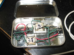
I made a stereo isolation audio transformer to solve this problem. The left and right channels enter a 1:1 600ohm audio transformer, which transmits the audio signal (which is AC) but blocks any DC connection. This prevents ground loops and currents between the two devices. I got the two transformers from old modems. One of the jacks is a fancy panel mount, the other is from an old sound card, and this old one is actually needed, because it is plastic, isolating it from the case, which is connected to the ground of the panel mount jack. Of course, I put everything in an Altoids tin.
I suppose it would also help if I put some ferrite on the inputs to also reduce RFI/EMI problems, but I haven't yet. Just having this device between a shortwave radio and a PC has reduced interference pickup quite a bit.
You can see more photos of the build at http://www.flickr.com/photos/dwarmstr/sets/72157604679420753/. Essentially, 1. Measure and Mark your holes. 2. Make a small punch to keep drill centered. 3. Drill a pilot hole, then the right size. 4. Solder the connections. I used a multimeter to figure out which connection was which on the transformers. 5. Hot glue for stability.
Parts cost: about $2.50 for the 3.5mm stereo panel mount. Everything else I scrounged for from old parts, not counting my time. Here's the equivalent commercial product at $32: http://www.amazon.com/3-5mm-Stereo-Audio-Isolation-Transformer/dp/B001GUS7EO. I do enjoy the look of that commercial case.
11 comments:
Hi Dean,
I installed a second-hand car stereo and amplifier and started to get the annoying hum from my speakers. I guess I have a ground loop problem.
I would like to try building my own audio isolation transformer using your design to try solving the ground loop, but how do I adjust the wiring using RCA input and output?
Thanks
Harris
You'll need four RCA panel mounts, with at least two of them being insulated from the chassis, like these: http://www.futurlec.com/RCA-PanelIns.shtml. RCA wiring is easier than the stereo jacks, because the left and right channels are separate. I used colored wiring in the project to specify things: red for the right signal, black for the left signal, and green for the signal grounds. You would connect RCA center pin and the shield connector to one side of one of the transformers.
I hope that helps.
I wonder what you are powering the car system with, as those are usually on a battery. If you are using a 12V DC wall-wart I could imagine some hum coming through it.
Great, yes it helps a lot.
I think I have an RCA panel mount lying around somewhere. I'll get right to it.
Thanks.
Harris
I did a google search for this and boy was this helpful!
I have a couple of questions though. I need to do this for a long component video run (basically 3 RCA cables) from one side of the room, up the wall to my ceiling projector. Since these will be analogue HD video signals I suspect I cannot use the same 600 ohm type transformers. Do you know what kind should I use?
Also, I really like the idea of making a balanced line from this setup and reversing the phase of one line and reconnecting the two lines--effectively removing any noise that gets on the line (at least that's what I understand). I just don't know how to do it (I'm fairly ignorant on electrical theory). So far all I see are pcb boards with opamps etc. Is there a simpler way with just some wires and transformers?
Thanks for the pictures and description. Definitely helped!
I just realized that I need to do this for my D-sub 15 from my computer as well. ARGGHH! So I guess that is even more complicated. If you know anything about that, that would be great too. If not, oh well. I guess I'll have to wait until I can afford the commercial $80 converter.
These transformers won't work for component video applications, or at least definitely weren't designed for such: they were made for 50Hz-5000Hz; and I got lucky for this audio use which is at most 20kHz bandwidth. The component video bandwidth is about ~30MHz.
DSL modem transformers should be good to 1 Megahertz and likely several megahertz higher if roll-off is allowed. But you still need more bandwidth. And you need transformers with a suitable matching impedance for your application: 75ohm is standard for video applications.
To convert from an unbalanced line to a balanced line you would need a transformer known as a balun.
I think these do not provide galvanic isolation though--if that is a need; you didn't mention if you had already connected the projector with RCA cables and found a ground loop problem.
For most people's setups, isolating the cable tv ground connection($12) is cheaper/easier than working to break the ground loop deeper in the setup.
Hi Dean,
Thanks for replying. I figured the transformers would not be suitable for video.
I am not using cable from the cable company. This is just from my PC and blu-ray player up to my projector. The outlet next to the projector is on a different circuit than the PC and DVD (which are on the same circuit). The electrical line and the video lines follow the exact same path up the wall. I don't know if it is ground loop or EMI and/or RF or all of the above. I notice a lot of sources for problems.
If using baluns for video then would the way to do it be to put one balun (reversed because the signal starts out unbalanced) at the PC or blu-ray player and then at the projector put the balun in the normal direction?
I see your point about this not being galvanic, but if the differential noise is removed do I care if it is galvanic? Or am I being to optimistic about this process removing possible ground loop noise.
I kind of like building my own from parts, but if I have to buy the right transformer for this, I'll do it--if it isn't more than $20. But it looks like major hunting to get the right transformer. I notice commercial baluns for projectors are over $200 a pair! yikes!
Thanks for helping me understand this.
Dayrl
Hi Dean,
Looking over some Balun drawings, I think these are galvanic. Although the negative signal from the unbalanced source is carried over, it is connected to the ground wire (or shield) which is never connected to the two 'balanced' (but out of pahse) lines. I don't know if that means it is galvanic, but there is no DC to the 'balanced' lines, they are created the same way your isolation transformer does its lines.
cheers,
Daryl
hi dean
i have designed a circuit to transmit the text message typed in my computer through a radio transmitter.my PTT part of radio is working but i m not able to inject audio output(from normal AUDIO JACK) of computer to transmitter. The audio input requirement of the radio transmitter is 600 ohm balanced audio input(-20 dBm to +10 dBm).kindly can you please suggest a transformer of proper rating which can solve my this problem .
thanks
Gurpreet
I read your Isolation Transformer blog it was so nice and thanks for blogging. keep Blogging. We are also Manufactures and Supplier of Isolation Transformer in Tamil Nadu, India.
Post a Comment